Article table of contents
- Introductory components
- Installing the CPU & memory
- Casing & installing the motherboard (aka mobo)
- Graphics, soundcard & add-on cards
- Internal & external media drives installation
- Cabling, PSU, case LED lights & power button
- Additional cabling for output ports
- Finishing touches, power on self test (POST) & BIOS
- Operating system installation (Win XP)
Additional cabling for output ports
So what’s all about the front panel output ports? These section focuses on connecting the connectors found at the front of your casing, these can be audio cables, USB, firewire ports to important items such as your power and reset button.
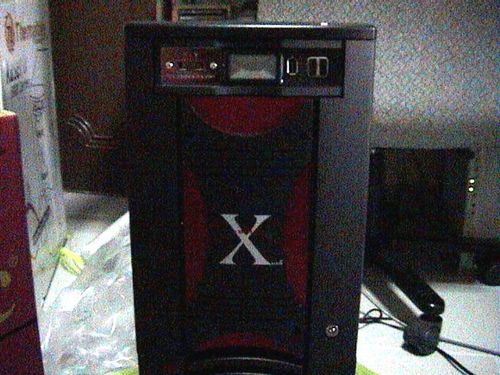
Nowadays, output ports are readily available as an good option for many DIY people out there. It allows external devices to be plugged in directly in front of your computer’s casing. The type of output ports can range from the all common USB to firewire, audio, parallel, game and serial ports. In fact, it’s safe to say that for any ports you find at the back, you are sure to find a similar panel option at the front. Some of them come integrated into the case itself, while some come in the form of add-on parts, such as the Thermaltake hardcano 7 in one such example spotting firewire and USB as shown below on the top of the casing.
Most motherboard manufacturers these days include expansion ports on top of those offered as standard at the back output of the motherboard. They usually come bare with pins on the board itself and require accessories such as an S-bracket or and external connector to route the input externally into a proper USB port, usually through specially fitting plugs which fits the pins. We usually see 2-4 additional USB port from these expansion pins, but the total number of ports too varies from motherboard to motherboard.
The motherboard I am using as an illustration here have 4 USB 2.0 ports at the back of the motherboard and 2 USB 2.0 expansion ports. Each USB port typically requires the following connection to work and they are identified as individual pins for each USB port (usually labeled USB0 and USB1, etc).
1st USB Port
- VCC
- USB0- (USB – Negative pin)
- USB0+ (USB – Positive pin)
- GND (ground)
- KEY (Optional)
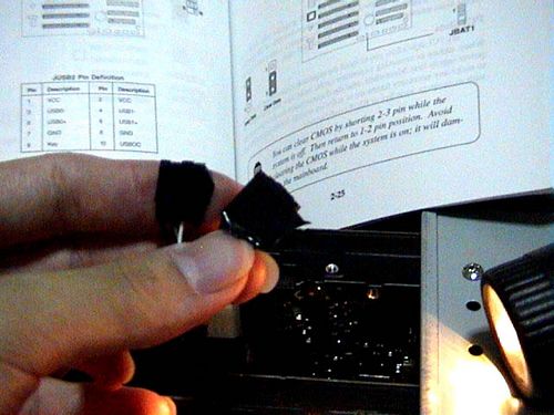
Consult your motherboard manual on its availability and also, to locate the pins to where the the extra USB ports can be connected. It should contain info like where the VCC, USB0-, USB+, Ground and key pins are located. Each (One) USB port requires you to connect to all the following 5 pins in total for each port. While some connectors come with a separate lead for each pin, some motherboards feature and assembled plug which you can simply just plug in one way without having to go through the connectors pin by pin.
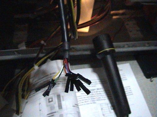
As shown on the left picture below, the connectors I’ve got from my Hardcano 7 USB output ports come in messy connector combination and not like those multi-pin pin connectors, where one plug is all you need to get one port working. Given this messy but flexible combination (as not all motherboard manufacturers have the same pin allotment, separate pins connectors are recommended to fit all different type of boards), you have to start on the painstaking task in plugging the connectors to the respective motherboard pins one by one.
Lucky for me, I decided to arrange the connectors in order as the pins shown on my motherboard. Then a simple dash of electrical tape to secure them altogether (on upper right fig) to keep them in order before plugging it with one easy short on the mobo. Do it so for all the ports you have and as simple as it is, it all pretty easy!
Other types of cabling
In addition to that, some output port panels do not necessary require you to mess with pins, but rather uses one of the your rear USB ports and extends the output to the front of your case into a hub. The same can be said if you wish to send an audio input (e.g like your microphone) or and output to the front, the most widely used way is to use a cable extender.
These extenders go from the front, through your whole casing and come out at the back slots and looping back to connect to your motherboard back output ports. This is useful if your board do not have the additional expansion pin port option and want to allow easy front connection of your back plate be extended to the front through of your enclosure’s front output port panel.
With these cabling done, we shall touch on the finishing touches for your system.
Article table of contents
- Introductory components
- Installing the CPU & memory
- Casing & installing the motherboard (aka mobo)
- Graphics, soundcard & add-on cards
- Internal & external media drives installation
- Cabling, PSU, case LED lights & power button
- Additional cabling for output ports
- Finishing touches, power on self test (POST) & BIOS
- Operating system installation (Win XP)