- Introductory components
- Installing the CPU & memory
- Casing & installing the motherboard (aka mobo)
- Graphics, soundcard & add-on cards
- Internal & external media drives installation
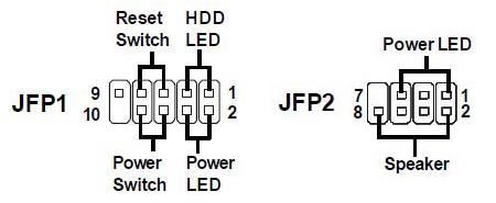
- Cabling, PSU, case LED lights & power button
- Additional cabling for output ports
- Finishing touches, power on self test (POST) & BIOS
- Operating system installation (Win XP)
Installing the CPU and memory
Your motherboard is the base unit which every thing else now is mounted and connected to, with it installed the first item you can start installing will be your computer’s central processing unit or CPU for short.
CPU install
The CPU (central processing unit) aka processor is the most important part of the computer. It happens to be the most sensitive too, so handle it with care.
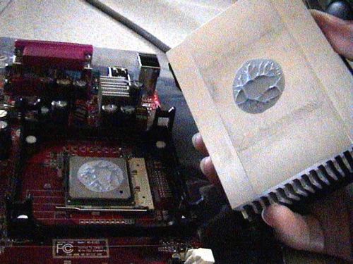
It would be easier to install the processor, heat sink and ram out of the system. Place the bare motherboard on a flat clean surface, remove the processor from the packaging and locate the processor socket on the motherboard, it should look like that in Fig 1.1 with the static bag placed below.
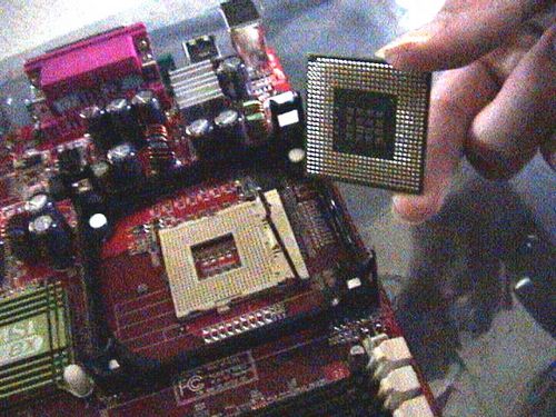
Note that the processor can only be slotted in ONE direction (identified with the pin counts and the cut edge on the bottom left of the chip) Put the processor above the socket and insert it gently. Excessive force will bend or break the processor pins.
Applying Thermal Compound
Thermal compound is of course much better than the inferior thermal pad provided with the heat sink. However, if you do not wish to apply thermal compound your unit, skip this step and head to heat sink installation part.
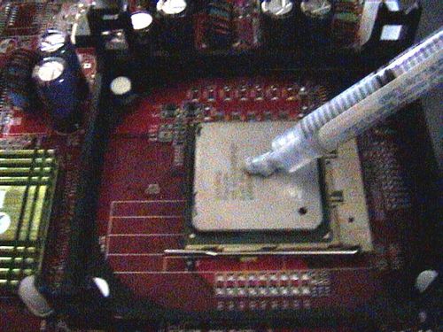
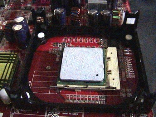
A small blot of thermal compound is only needed by a processor, (In Fig 1.3) unlike thought by many- more is not always better in this case.
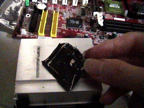
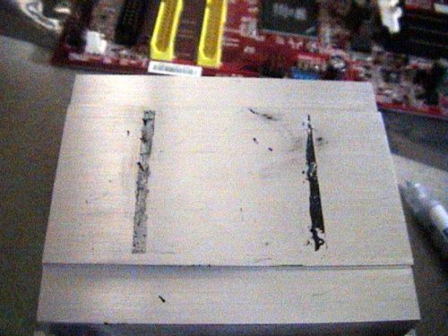
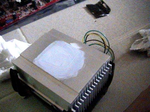
As shown above, I’ve gone on the task of peeling the damn pesky thermal pad of the heat sink. Try not to touch the black surface as it contains thermal conducting paste as well. If it were to stain your heat sink (Fig 1.4) wipe it off with dry fingers. This is one stain where water and tissue is unable to remove.. strangely enough.
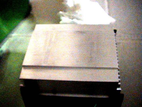
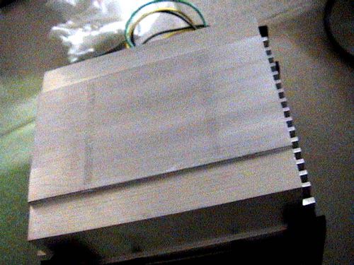
Once the heat sink is clean, gently lower the it over the processor (with your previously applied thermal compund) and gently press the two surfaces together till you get some thermal compound onto the heat sink (Fig 1.5) Remove the heat sink (note that you will get equal amounts of thermal compound on both the heat sink and processor) Next, using a CLEAN finger or your finger wrapped with a clean transparent plastic bag, slowly spread the compound all over the surface of the heat sink which you think, will be in contact with the processor. Keep spreading with a massaging & rotating pressing motion until all the compound is thinly compacted and evenly spread on the heat sink (Fig 1.6)
After that, use a tissue paper and wipe off all excess thermal compound from the heat sink with only 1 or 2 straight clean swipes. Note that upon doing that, you will notice a nice stain on the heat sink produced by the compound (blue in my case) which you can’t wipe off. This is because all the thermal compound you’ve just applied, had all entered the microscopic gaps or crevices of the heat sink metal surface. This is to ensure optimum heat conduction.
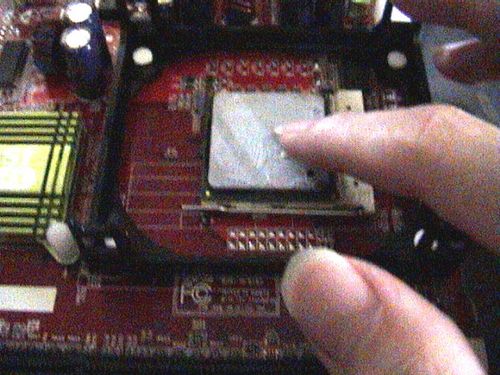
Back onto the processor, using a clean finger or one wrapped in a plastic bag, spread the thermal compound throughout the top surface evenly and thinly until it it is uniformly thin on the processor surface, as shown below:
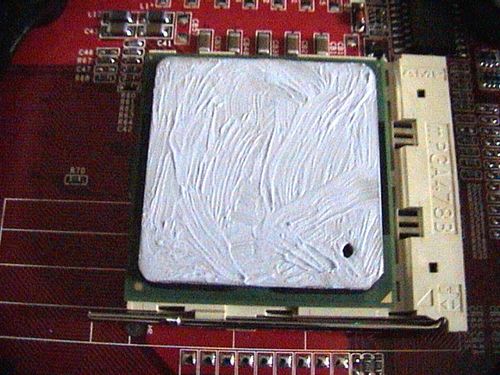
Next for tidiness, use a clean razor or plastic card to scrape of overflowing excessive compound from the processor edges, leaving only the paste on top of the processor itself. The thermal compound application is done.
Heatsink Installation
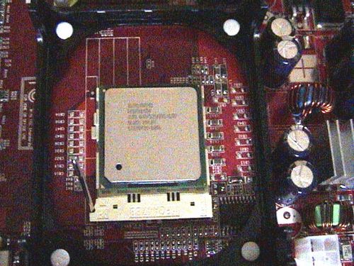
The thermal compound serves as a high grade conductive medium, allowing effectively heat dissipation to the heat sink. When all is done, take the fan and heat sink unit, place it above the motherboard guiding rails and lower is down straight, latching it to the motherboard. Do not perform twisting or any torsional motion downwards as you could smear or potentially mess up the evenness of the the thermal compound. Again, simply just slide the attachment straight down. You might want to give the fitting a some practice tries before actually allowing the heaksink to touch the processor, unless you are sure you can get the heat sink to lock on your first attempt.
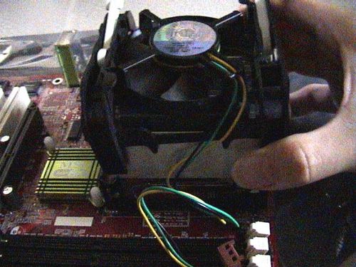
Once in place ensure that all holder four latches are in line and secured, thereafter, lock the plastic fan holder containing the heatsink onto the motherboard by locking the plastic levers at the top of the processor assembly, they usually go in opposite directions.
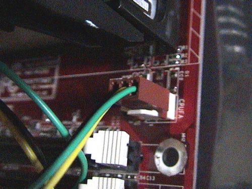
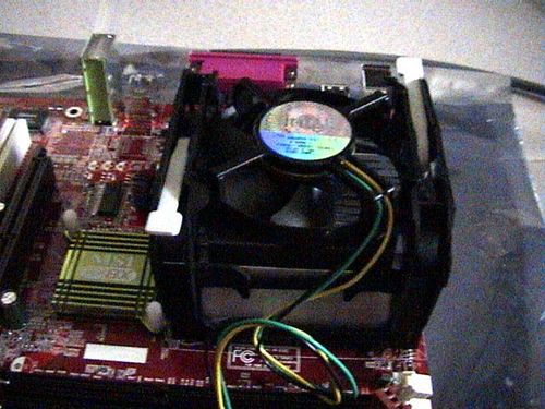
Fig 1.7
Slotting in the RAM
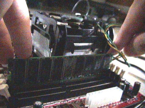
Finally, take the lose CPU fan power cable and connect it into the CPU fan power plug on the motherboard (Fig 1.7). In doubt, simply just consult your motherboard manual on the location of the fan power plug, it differs between manufacturers. But be rest assured, its always situated near the CPU socket itself.
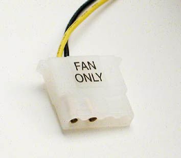
There is usually an additional fan output called the system fan (or sysfan0). If you require a fan with variable RPM and can be automatically controlled by your system, you can use this fan at your own discretion, only that you might need to get a molex converter or a 4 to 3 pin converter if you are to use a conventional delta fan. Otherwise, you can ignore this if you are intending to plug your case fans directly into your PSU or a controller of your own.
Installing the RAM
Now onto the RAM, take the ram module and slot it firmly with both hands on each end into slot one (usually nearest to the processor). If the the end latches don’t lock when its slotted, either you have to do so manually or the ram module is not slotted properly. All RAM modules are relatively fool-proof and can only go in one direction, all you need to do is to match the pins length on either side of the DIMM with the motherboard slots. Also, note that the first RAM slot on the motherboard must be always occupied even if the rest aren’t, so always slot them from the first DIMM slot and down.
If you intend to use dual channel RAM, ensure that your RAM modules are of the same make and capacity and slotted in pairs on the same channel for it to work. The slots are usually colour coded and you are usually fine slotting the 2 Modules within the same colour group.
Again consult your motherboard manual on the DIMM slot numbers if you are unsure about that.
- Introductory components
- Installing the CPU & memory
- Casing & installing the motherboard (aka mobo)
- Graphics, soundcard & add-on cards
- Internal & external media drives installation
- Cabling, PSU, case LED lights & power button
- Additional cabling for output ports
- Finishing touches, power on self test (POST) & BIOS
- Operating system installation (Win XP)

")