The site’s pretty well much up and running already. Dude, did the tons of php coding on the blog entry and comments section- sure kinda whocked me up in the afternoon, till I got it fixed after dinner. Added cookies functions so you don’t need to retype your nick and stuffs each time you post any comments, keke, so much for THE SITE… Moreover…and.. damn, will be waking up early for the first time in 2months for some NS vocational assignement thingy at science park tomorrow morning, hope I can fall alseep by 12 tonight, cos normally 2am is my usual bedtime *duh* gotta stop drinking coffee already.
Design Version 10 up!

Ok, as promised, V10.0 is up dudes! feel free to romp around the site.
In the meantime, I have to adjust some pages to fit the new color scheme, so please bear with it. Also, a comments section is up, but its still very very buggy.
Me? Linksys winner?
Lolz, won in some little Linksys lucky draw, me puzzles of how I entered.. then, yea must be danged router I’ve brought from them last year… hehheh.. got the 10th prize linksys gift pack.. *duh* check out this link, and yea my name’s there too. When you come to think about it, in the whole of Singapore, mmm, out how many people who brought linksys products, about 80 ppl won…MMmmm..
dang! mind my babbling! cos I am thinking bout the math involved and the probalblity of winning.. *DUH again* sips coffee to get me going.. well, its just lucky me…
Ok, on the site. I have the lastest design finalised tomorrow, noon (the time which I normally wake up in mornings) the colour scheme you see here (yellow, black) is a small preview to what you can expect tomorrow. In the mean time, take time to appreciate ver 9.0, cos v10.0 is here to RULE.
Woo news page up!
This is a news test page. The news section will be up on friday afternoon (8+ GMT). Sorry for any inconvience caused
Functional check 2
Got the new blog system up, ported from my previous databases, so here goes, test test testing, 1, 2, 3.

Build your own personal computer- Finishing touches and POST

Article table of contents
- Introductory components
- Installing the CPU & memory
- Casing & installing the motherboard (aka mobo)
- Graphics, soundcard & add-on cards
- Internal & external media drives installation
- Cabling, PSU, case LED lights & power button
- Additional cabling for output ports
- Finishing touches, power on self test (POST) & BIOS
- Operating system installation (Win XP)
Finishing touches, power on self test (POST) and BIOS
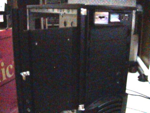
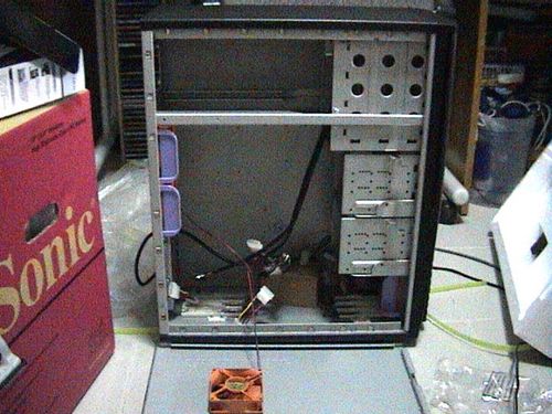
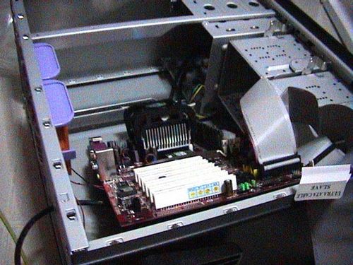
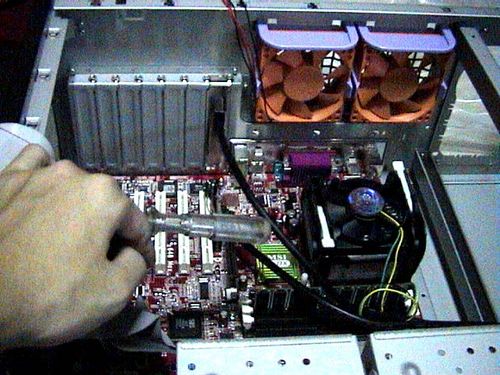
Now to do alittle house keeping before closing up your PC enclosure. Here I will talk about good internal wire placement and layout. It is generally good to keep power cables arranged neat and in order so as it does not obstruct heat dissipation, air flow and operation of moving parts (e.g. fans). As you can see, after assembling the PC, the case is very much like a big Medusa mess of wires.
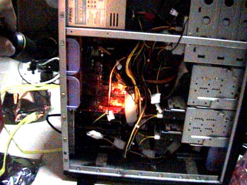
Though your system can run in this mess and may seem insignificant now, it goes a long way in promoting smoother, cooler internal operation resulting in fewer lockups, lesser equipment failure and longer equipment life. Improper ties cables can get caught in your fan blades, cause necessary noise or vibrations of even create pockets of air spots which built up internal case temperatures over prolonged use.
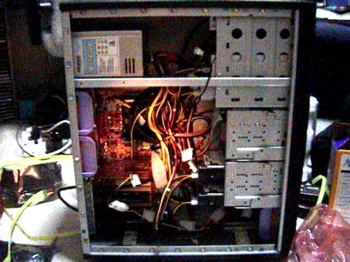
You can always tidy up the case using cable ties, the general rule is to make all areas where air flow is evident, that is the suction and exhaust areas near the fans. Air generally gets sucked in from the front of the case and blow out at the back, the air flows over your processor and graphic card, which are major heat generators as well as your hard disk, so you do not want any obstacles in the way of this air flow.
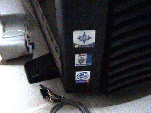
Once done, the following are all cosmetic clean ups, like exterior touch ups are kinda fun thing to do too, first with the pasting of the “all important” intel and motherboard stickers.
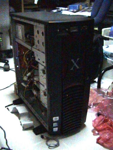
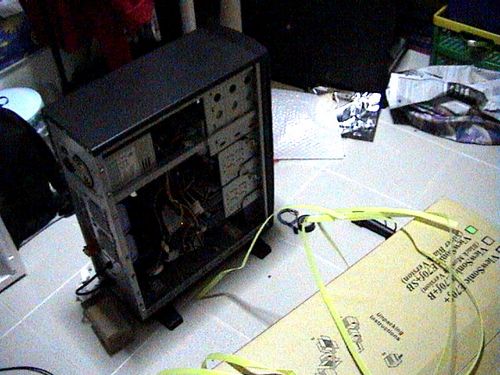
Building your PC can create quite a mess where you are, if tidiness is your cup of tea, you might want to tidy up the area before booting up. Ok with that lets get on with booting up this system.
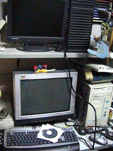
Now is the magic moment we had been waiting for, making sure your system actually works. Start by plugging in all your required input and output devices, such as monitors, keyboards and mice, ensure they are all powered on and standby. If you have audio, plug in your 3.5mm audio cable and power on your speakers, the same for network with wireless or ethernet cables.

POST
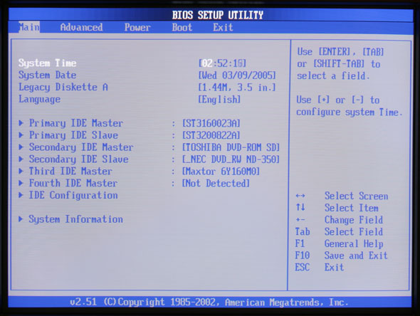
The post (power on self test) is the first thing you see when you first boot up your computer, and that the time when the computer checks for all the connected components, (processor, amount of ram, connected drives.. etc). If you can see the start-up screen and you enter the bio setup, its an indication that everything’s all set right and you can go onto installing your operation system. If everything is ok, the system will just go through all the component checks and eventually stop after the IRQ check or so. The system will continue in this loop until you specify a boot device, which is configurable in the BIOS which I would touch on soon.
What to do if you see nothing on screen
If you do not see anything on-screen after turning the unit on, look for symptoms: Are the fans spining? any harddrive activity? or is your video card not properly inserted? such small tell tale signs can lead you to the problem. Turn off the computer, unplug the main power cable and check that all connections (video, power connectors, add-on cards) are secured and properly plugged in. Do a thorough check on all components and be sure on that. When you are done, close everything backup, plug in power and retry.
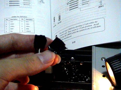
If you’ve got everything checked, it is sometimes ideal to reset/clear your CMOS and restart the POST procedure again, it can be done by shorting the CMOS (JBAT1) connector jumpers on your motherboard. (do so when your computer is off and mains power off, or you can get permanent board damage).
As always, consult your motherboard manual if you are in doubt where the clear CMOS jumpers are.
The BIOS
In the BIOS (basic input and output system), you can check the number and type of hard disk, CD-ROM drives you’ve connected, so are the processor info, type and amount of ram you have, this is useful for checking on connections. Included too, are certain diagnostics tools if your board have that feature. You too, can enable of disable certain additional properties such as SMART for hard disks, quick boot feature etc, enable/disable plug and play, on board integrated sound if you intend to use a separate sound card for audio output.
One important thing to do here is to change the boot sequence of your computer if you intend to install an operating system later. If you are using Windows 7, Vista or XP, Linux, FreeBSD, etc, set the first boot device to CD-ROM, for windows 98 and thereafter or alternative, you need a boot up floppy for installation, so select floppy drive as the primary boot drive. Some newer motherboards will auto detect and select a boot device based on what is detected let be installing from a mass storage device or a thumb drive as well, so sometimes it can be done automatically, though you might want to set the option manually and not leave it to chance.
Just explore around, who knows the your BIOS may have some unexpected new features, use the manual as a guide if you do not understand certain technical terms, its always there.
Advanced BIOS tweaking and overclocking
You can fine tune your system by changing certain processor core voltage, graphic card voltage, memory latency for improved performance. If you do not intend to do an overclocking or so, just leave everything as the preset default or normal settings as this is not recommended in the preliminary rounds of setting up your new system. But you can do so after you’ve got the system set up and stable.
With your system up and running, it is now ready to accept the operating system install to get it up into a system which you can actually use.
Article table of contents
- Introductory components
- Installing the CPU & memory
- Casing & installing the motherboard (aka mobo)
- Graphics, soundcard & add-on cards
- Internal & external media drives installation
- Cabling, PSU, case LED lights & power button
- Additional cabling for output ports
- Finishing touches, power on self test (POST) & BIOS
- Operating system installation (Win XP)
Build your own personal computer- Additional cabling for output ports

Article table of contents
- Introductory components
- Installing the CPU & memory
- Casing & installing the motherboard (aka mobo)
- Graphics, soundcard & add-on cards
- Internal & external media drives installation
- Cabling, PSU, case LED lights & power button
- Additional cabling for output ports
- Finishing touches, power on self test (POST) & BIOS
- Operating system installation (Win XP)
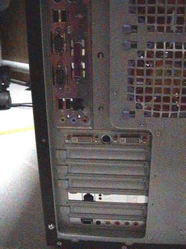
Additional cabling for output ports
So what’s all about the front panel output ports? These section focuses on connecting the connectors found at the front of your casing, these can be audio cables, USB, firewire ports to important items such as your power and reset button.
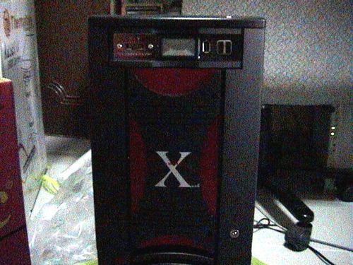
Nowadays, output ports are readily available as an good option for many DIY people out there. It allows external devices to be plugged in directly in front of your computer’s casing. The type of output ports can range from the all common USB to firewire, audio, parallel, game and serial ports. In fact, it’s safe to say that for any ports you find at the back, you are sure to find a similar panel option at the front. Some of them come integrated into the case itself, while some come in the form of add-on parts, such as the Thermaltake hardcano 7 in one such example spotting firewire and USB as shown below on the top of the casing.
Most motherboard manufacturers these days include expansion ports on top of those offered as standard at the back output of the motherboard. They usually come bare with pins on the board itself and require accessories such as an S-bracket or and external connector to route the input externally into a proper USB port, usually through specially fitting plugs which fits the pins. We usually see 2-4 additional USB port from these expansion pins, but the total number of ports too varies from motherboard to motherboard.
The motherboard I am using as an illustration here have 4 USB 2.0 ports at the back of the motherboard and 2 USB 2.0 expansion ports. Each USB port typically requires the following connection to work and they are identified as individual pins for each USB port (usually labeled USB0 and USB1, etc).
1st USB Port
- VCC
- USB0- (USB – Negative pin)
- USB0+ (USB – Positive pin)
- GND (ground)
- KEY (Optional)
Consult your motherboard manual on its availability and also, to locate the pins to where the the extra USB ports can be connected. It should contain info like where the VCC, USB0-, USB+, Ground and key pins are located. Each (One) USB port requires you to connect to all the following 5 pins in total for each port. While some connectors come with a separate lead for each pin, some motherboards feature and assembled plug which you can simply just plug in one way without having to go through the connectors pin by pin.
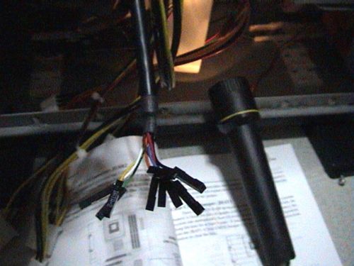
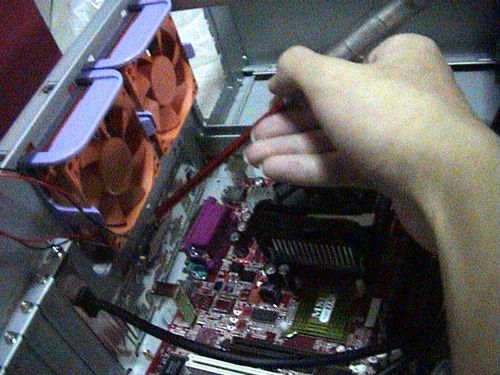
As shown on the left picture below, the connectors I’ve got from my Hardcano 7 USB output ports come in messy connector combination and not like those multi-pin pin connectors, where one plug is all you need to get one port working. Given this messy but flexible combination (as not all motherboard manufacturers have the same pin allotment, separate pins connectors are recommended to fit all different type of boards), you have to start on the painstaking task in plugging the connectors to the respective motherboard pins one by one.
Lucky for me, I decided to arrange the connectors in order as the pins shown on my motherboard. Then a simple dash of electrical tape to secure them altogether (on upper right fig) to keep them in order before plugging it with one easy short on the mobo. Do it so for all the ports you have and as simple as it is, it all pretty easy!
Other types of cabling
In addition to that, some output port panels do not necessary require you to mess with pins, but rather uses one of the your rear USB ports and extends the output to the front of your case into a hub. The same can be said if you wish to send an audio input (e.g like your microphone) or and output to the front, the most widely used way is to use a cable extender.
These extenders go from the front, through your whole casing and come out at the back slots and looping back to connect to your motherboard back output ports. This is useful if your board do not have the additional expansion pin port option and want to allow easy front connection of your back plate be extended to the front through of your enclosure’s front output port panel.
With these cabling done, we shall touch on the finishing touches for your system.
Article table of contents
- Introductory components
- Installing the CPU & memory
- Casing & installing the motherboard (aka mobo)
- Graphics, soundcard & add-on cards
- Internal & external media drives installation
- Cabling, PSU, case LED lights & power button
- Additional cabling for output ports
- Finishing touches, power on self test (POST) & BIOS
- Operating system installation (Win XP)
Build your own personal computer- Internal and drive installation

Article table of contents
- Introductory components
- Installing the CPU & memory
- Casing & installing the motherboard (aka mobo)
- Graphics, soundcard & add-on cards
- Internal & external media drives installation
- Cabling, PSU, case LED lights & power button
- Additional cabling for output ports
- Finishing touches, power on self test (POST) & BIOS
- Operating system installation (Win XP)
Internal and external media drives installation
This part now talks about the installation of your internal & external media drives, this includes your CD/DVD-Rom drive as well as your hard disk drives.
Preparing to install
First off, for most cases, it is always common to have the larger 5.25″ bays (for mostly cd-media drives) ontop of the 3.5″ bays (for floppy and hard disk drives), this is better as most ATA cables (which connects to your harddisk) are generally shorter than that of other IDE cables which connects to your external media drives, though longer ones can be always purhased at any local hardware store.
Also, generally, the way you install the drives on your computer depends greatly on the design and features it have (eg, availability of rack rails, drives cages, etc) and it differs from one type of casings to the other. Brands like Cheiftec, Lian-Li, Antec and Thermaltake are better case makers out there and have better installation features.
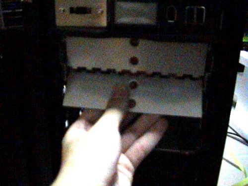
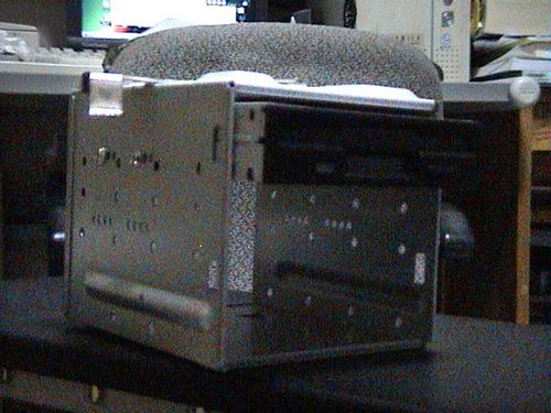
On the casing I am using(Fig 5.1), we can see that all bays all are covered by a a sealing plastic cover. To remove these covers, just release the locking hatches behind them through the interior of the casing. Some case manufactures like thermaltake also have pre-casted steel protection plates behind the covers (Fig 5.2), and can be easily removed with some simple twisting motion (similar to that of removing pieces from plastic model kits)
With all that done, lets prepare the drives themselves. Harddisk these days come with 2 types of connectors for mainstream computers- SATA and PATA, generally SATA is an improvement of parallel ATA or P-ATA for short, it rated at ATA-100/133 while SATA can go up to ATA-150. Nafive to PATA drives is the need of the trademark IDE ribbon cable which in turn requires jumpers to be set properly on the integrated drive electronics (SATA harddisks do not have jumpers).
Drive jumpers
Ok, onto the jumpers, jumper configuration differs from drive to drive, and luckily, almost all manufacturers have the jumper settings printed onto the drives themselves. These are usually located at the back of the drive where the connector pins are, look for a sticker stating the position and orientation fo the jumpers to set the respective MASTER or SLAVE option, it;s fairly straightforward. Usually upon purchasing a drive, it is usually set to the MASTER setting by default.
If you intend to install a second drive using that same motherboard slot, the 2nd drive must be set to the SLAVE jumper setting in order to function. You have to remove the jumper and rearrange it in accordance of the set up diagram provided by your manufacturer. To remove jumpers use a screwdriver (or alternative sharp object), gently lift the jumper out of the pin slot and later, place it back in the defined SLAVE setting.
Internal hard drives
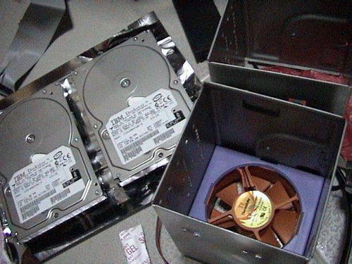
I am intending to use two hard drives for this system. As stated, this casing have removable hard drive cages, which makes installation easier by mounting drives out of the system and locking the cage back in when done, thus no need to cramp within the confined boundaries of the interior and securing in the hard disk to metal frames internally. Some cases have a better evolved system where you can simply just slide the drive into bays already made for hard disks and simply just click them into place without tools, so it varies between manufacturers. If your system have no cage feature, don’t fret, just follow on the review on installation, only that you have to do it within the fixed bays in your casing.
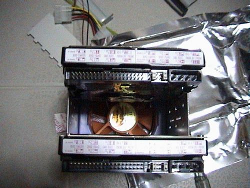
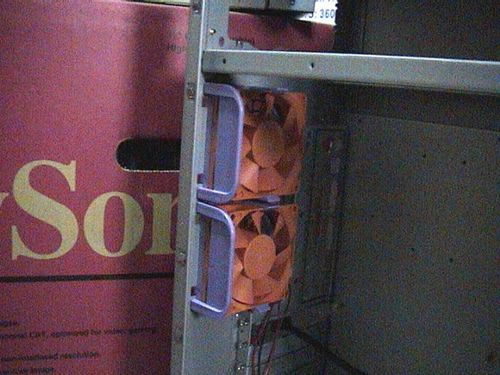
As we can see below, thermal take has included a single cooling fan in one of the harddrive cages (Fig 5.3) which can accommodate 3 hard disks. These drives can run pretty how after sometime, so the general tip here is to install the drives in a manner which allows the maximum airflow on either side of the drive. If you are installing one hard disk, it would be ideal to install it in the center of the cage, where air blowing from the fan can flow both above and below it, thus providing better and more effective cooling. For 2 drives, one would go on the top while the other, at the extreme bottom of the 3 available mounting places, (Fig 5.4) where airflow is still possible between them.
I have no intentions to do a water-cooled system on this computer so fans would do great at the moment, anyway I find water-cooling your harddisk enclosures bit of an overkill as you can’t actually “overclock” these babies, and why should you?
External CD-media drives
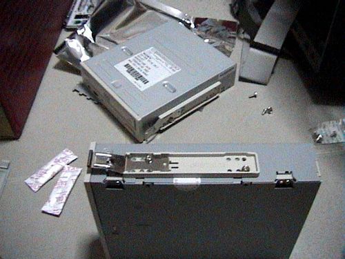
Removing the 2nd 3.5″ harddrive cage (fig 5.5), this is where you can install additional hard disk or any 3.5″ external drives such as a floppy drive or a multi-card reader, in this case, it would be used to hold my floppy disk drive.

Now to install the DVD and CD drives, we focus our attention to the 5.25″ drive bays above. With front the metal plates removed on fig 5.6, time to install them.
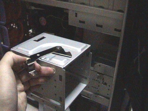
The 5.25″ drive bays are little different from the 3.5″ cage, the casing employs Chieftec rails to rack mount the bay drives, which are stored within the casing itself to prevent misplacement. Before happily screwing in the rails, you have to locate the right depth alignment of your rails and your drive, or your drives will either stick too far out, or too shallow of the casing. You need a little trail and error for this.
While holding the rails beside the drive, test-slot the drive into your casing to locate the rail holes where the screws go in nicely on to your drive, remove it and secure the rails onto the drive with respect to those holes themselves. Do so for all drives you intend to install and just slot them into any 5.25″ bay slot you seem fit.

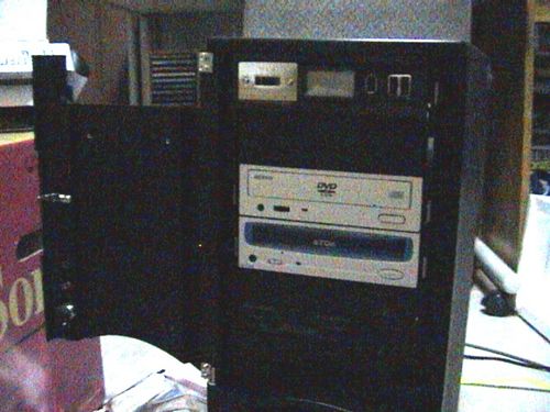
After you are done, the drives can be removed without tools by simply unlocking the rail clips and sliding the drive out. Perfect for quick drive swaps. With all drives done now to it’s time to wire them all out.
Article table of contents
- Introductory components
- Installing the CPU & memory
- Casing & installing the motherboard (aka mobo)
- Graphics, soundcard & add-on cards
- Internal & external media drives installation
- Cabling, PSU, case LED lights & power button
- Additional cabling for output ports
- Finishing touches, power on self test (POST) & BIOS
- Operating system installation (Win XP)
Build your own personal computer- Graphic and add on cards

Article table of contents
- Introductory components
- Installing the CPU & memory
- Casing & installing the motherboard (aka mobo)
- Graphics, soundcard & add-on cards
- Internal & external media drives installation
- Cabling, PSU, case LED lights & power button
- Additional cabling for output ports
- Finishing touches, power on self test (POST) & BIOS
- Operating system installation (Win XP)
Graphics, Soundcard and addon cards
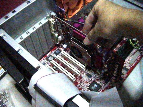
Installing cards are considered one of the most easiest things to do on DIY, it is just mostly locate, align, slot, align and secure. For most cases, you will require just a basic screwdriver to secure the cards in place on the rear mounting slots of your case itself. If you enclosure feature plastic tool-less clips for card installation, the better. Just follow this few ‘golden rules’ and you will be fine for all kind of cards in general.
Graphic card install
Modern day motherboards should have at least a graphics port slot it can come in PCI-E or AGP formats for older boards. It can be identified as the slot closest to the processor or north bridge or the only port with a locking mechanism. It is also usually the shortest port and is normally located on the top of the line of PCI slots. Other performance boards can feature dual PCI-E slots either in PCI-E 1.0 or 2.0 to allow SLI or crossfire configurations. For 2 and up to 4 GPUs to be linked together.
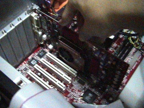
Optimal card placement
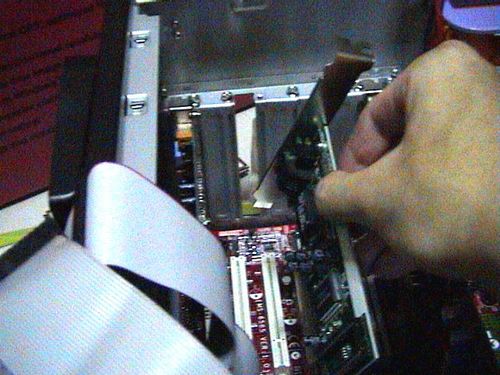
What I am focusing here is nothing much on how to find the best way to install an add-on card or the nicest way of slotting it in, but locating strategic locations for your card. You do not have a choice in the location of the graphic card slot, you however, have a choice on the location for the PCI add-on cards and if you have any, you might want to place them as far as possible from each other.
Having said that, the best location for any add-on card with proximity to your graphics card is at least one or 2 PCI slots away from it. As a video card is essentially a mini PC with it’s own processor itself, it dissipates a lot of heat in operation and breathing space is necessary. This is further more paramount if you intend to do some overclocking. Moreover, extensive amounts of heat from a nearby adjacent card can cause an unnatural build up of operating ambient temperature, which is not efficient technically and might do significant damage of even shorten the lifespan of the cards placed close together. So place great caution on the location of your cards.
Miscellaneous add-on card
Add-on cards will encompass any additional cards plugged in either on the motherboard PCI or mini PCI-E slots, usually for added functionality for the system. For example e.g. Wireless network card, FM/Digital TV Tuner, firewire PCI card and sound cards are few of them.
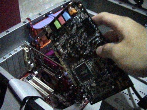
For my sound card in this case- a Creative sound blaster Audigy card (Fig 4.1), good place to install it in the case is at the bottom row of the PCI slots, leaving a more than enough 5 PCI slots between them for optimum heat flow and better performance. Anymore additional cards will go in between this space. If you have a network card or say a TV tuner, it’s relatively safe to place these cards side by side slotted next to each other as they do not release much heat when in operation.
With the add-one card installed, lets head onto the media drives installation next.
Article table of contents
- Introductory components
- Installing the CPU & memory
- Casing & installing the motherboard (aka mobo)
- Graphics, soundcard & add-on cards
- Internal & external media drives installation
- Cabling, PSU, case LED lights & power button
- Additional cabling for output ports
- Finishing touches, power on self test (POST) & BIOS
- Operating system installation (Win XP)
Build your own personal computer- Casing and motherboard

Article table of contents
- Introductory components
- Installing the CPU & memory
- Casing & installing the motherboard (aka mobo)
- Graphics, soundcard & add-on cards
- Internal & external media drives installation
- Cabling, PSU, case LED lights & power button
- Additional cabling for output ports
- Finishing touches, power on self test (POST) & BIOS
- Operating system installation (Win XP)
Casing and installing the motherboard
With the processor mounted on the board, it’s time to mount the motherboard into the case itself. This have to be done before the introduction of the various components I will be using thereafter. So lets get on the next step of actually building the PC. Once in, all the various components can follow and be connected to it.
First off, the casing
The casing is one of the most important unit of the whole PC, as of course it houses all the necessary components for operation. Well, unless if you want to run your bare PC case less, that’s an exception- This is one thing you shouldn’t miss. Going into more detail on the casing now, this Thermal take casing I’ve got is a mid-tower server casing which can take ATX sized boards or larger. M-ATX are compatible too as well given the standards for dimensional mounting holes across all sizes of motherboard.
It have four 5.25″ external bays, two 3.5″ and four 3.5″ internal bays (removable bay cages).
This is an air cooled case, so fans will be the talk of the town here. Fan wise, Thermal take has really decided to put all they’ve got into their first line of casing, firstly with their fans. At the front we have one single fan mounted in one of the hard drive removable cages. There is also one as a standard system fan at the bottom front. At the side, we have one side blowhole intake fan mainly used to blow fresh air into the processor and graphic card area.
The exhaust fans
Front SOHO style doors
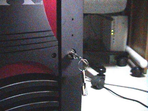
Lock and key
At the back, there are two exhaust fans primary used to expel heat from the processor and board components.
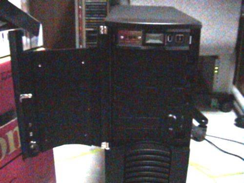
Ok, now to the front exterior- and say!.. they’ve even included a lock and sets of keys for the front and side door. This door is heavy- made completely of bolted solid steel with several metallic pieces mounted and screwed together, giving it that very solid sleek finish. It’s just a pity that for a door this solid, it’s let down by a dingy plastic latch which is the swiveling attachment for the key lock.
Getting the Motherboard in
First off, one the the main things we have to check before happily screwing the alignment of the board is the back output panel. Obviously, most case-manufacturers do not know what kind of boards you are using and always include a standard output panel which don’t always seem to fit your configuration. That is when the mobo manufacturer come to the rescue- by including in the package, their own cut out panel.
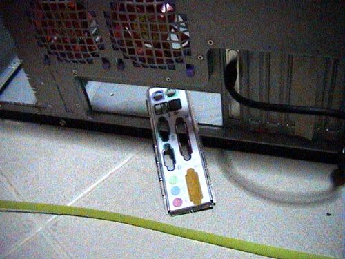
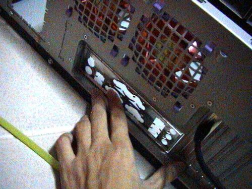
To remove the original back panel, gently use a screwdriver to poke the small securing popped out dots around the edges of the aluminum panel, do so for about majority of them on each side and the a final jerk will force it out nicely unharmed. These back panels are usually tacked evenly around it’s circumference, so just knocking them out will be good enough. One you’ve got that generic panel out, clip in your own glove fitting back panel as provided by your motherboard manufacturer.
Once you’ve got that settled, check the internal side surface of the casing for motherboard spacers (These are the golden stubs we see in Fig 3.2). Spacers are screws which screws in one end and have openings at the top that allows other screws to be mounted onto them. Such spacers are used to actually, space the board from the being in contact with the casing surface. If the casing manufacturer hasn’t pre-screwed them in for you, pop in the motherboard & locate the alignment of mounting holes from your motherboard with the drilled holes on your casing panel and screw them in appropriately.
After getting the spacers in, slowly lower the motherboard on them (Fig 3.3) and get the output motherboard ports to stick out of the back panel. (Fig 3.4) Everything should go well and fit like a glove as most casing and motherboard makers adhere to the same standard ATX dimensions on screwing holes, alignments etc.
Finally, start on the repetitious task of securing all the screws securely into the spacers themselves. It took me quite some time getting all the nuts in, but maybe I think it was just me as its not easy holding the board with one hand and screwing it in freely with the other! When the board and processor finally in and secured. Give yourself a pat on the back you’ve cleared one major huddle. it’s time to add the add-on cards next.
Article table of contents
- Introductory components
- Installing the CPU & memory
- Casing & installing the motherboard (aka mobo)
- Graphics, soundcard & add-on cards
- Internal & external media drives installation
- Cabling, PSU, case LED lights & power button
- Additional cabling for output ports
- Finishing touches, power on self test (POST) & BIOS
- Operating system installation (Win XP)
Tutorial: DIY steps to build your own personal computer- Introduction

About this tutorial
Welcome to the DIY workplace. This article primarily serves as a written guide for anybody out there who intends to DIY his/her PC. As I noticed an increasing trend of people moving away from boutique/big branded PCs, turning to cheaper home built alternatives, so why not write an article which are both useful and helpful?
I’ve included detailed steps and tips mainly on the construction of the computer itself with pictures captured real time when building my own PC. The tutorial is split in 9 distinct parts, each focusing on a specific part of the build process and component of the computer well, you can skip to any part you wish through the tutorial or follow through page by page.
Article table of contents
- Introductory components
- Installing the CPU & memory
- Casing & installing the motherboard (aka mobo)
- Graphics, soundcard & add-on cards
- Internal & external media drives installation
- Cabling, PSU, case LED lights & power button
- Additional cabling for output ports
- Finishing touches, power on self test (POST) & BIOS
- Operating system installation (Win XP)
For beginners and advanced users as well
This article teaches the basics and is applicable most makes of computer hardware components due to the standards in the hardware manufacturing industry (eg like using AMD based processors, even if an Intel one is used here, i.e most hardware components like motherboards, video cards.. etc, very similar in their basic forms over the many manufacturer’s makes or formats eg ATX, BTX, FlexATX or Mirco boards…etc). Always make sure that your hardware are rated to work with each other, taking note of these few basic but crucial pointers for a system to run:
- Using an commercial AMD socket based motherboard for AMD processors, and an intel one respectively for commercial intel boards.
- An AGP based video card for an agp slot and not a PCI card (which are kinda rare these days), since AGP 8x cards are mostly backward compatible using such a card on old agp boards are completely ok.
- Right ram speed for the chosen motherboard, always stick the the right rated memory frequency (say your PC ratio is 3:2, memory speed is calculated from your front size bus speed divided by 3, your CPU multiplier then multiplied by 2) and type, going under will undermine performance while going too high might even result in crashes or system instability. Of even worst, choosing the wrong format (i.e DDR3 to DDR2, RDRAM instead of SD or DDR SDRAM).
- All cables (internally and externally) MUST be secured and not left loose.
- Do not use force on the components- hardware are fragile and very sensitive (besides static damage) shocks must be avoided on all parts, as they are all designed to be fitted smoothly with ease.
- Do not overclock components unless have the proper cooling equipment and/or prepared for the risks involved, not to mention voiding most of warranties.
Take note and check your hardware’s compatibility before buying from the store, when in doubt always consult the store assistant.
Always be patient, esp if you computer don’t boot the first time you’ve assembled it, keep your cool and troubleshoot, going through each part whether they are secured, properly inserted, loose, damaged.. etc.. also, always keep that motherboard manual handy at all times, you will need it. With that in hand lets go on building your new PC.
Components
Here are the big daddies of what you need on a very basic level to get your system up and running.
Processor
Here I have an old Pentium 4 2.53Ghz. Much has improved over the years in miniaturizing them. This processor is really smaller than what I’ve expected, taking into consideration that I’ve been using Intel socket7 i430VX and AMD K6 processors for all the time. Most reviews online always have them so big though!
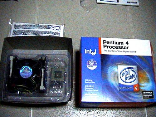
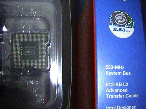
This is a comparatively neat and intel has done to minimize processor size down to the 0.13 mircon process, with 512KB L2 cache, 522Mhz FSB. The package contains 2 main packages, a sealed plastic molded container containing the 2.53Ghz processor, the official fan and heatsink and thermal pad (which I will be replacing with the Nanotherm Blue II ceramic thermal paste) with a plastic package behind containing authenticity info, warranty and the P4 sticker.
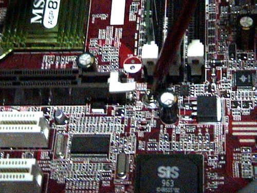
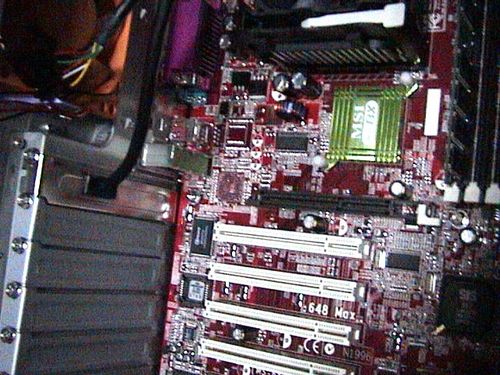
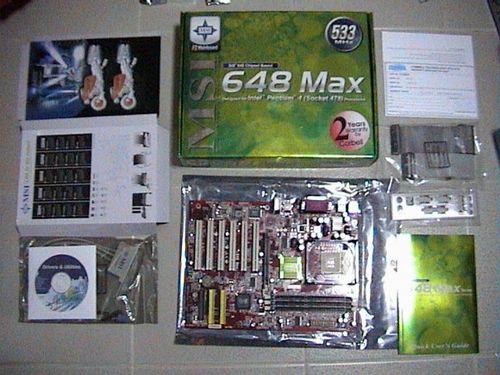
Motherboard
Msi 648MAX (sis648 chipset) Ok, down the the mobo. Its quite nice to know that they had included the d-bracket for usb port mounting.. on the other hand, I don’t think that is necessary as the thermaltake XaserII casing I am using already have 2 USB ports on the front. Good thing they’ve catered to all, but not all needs.
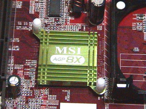
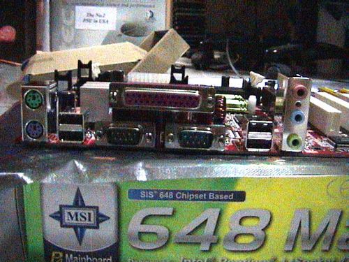
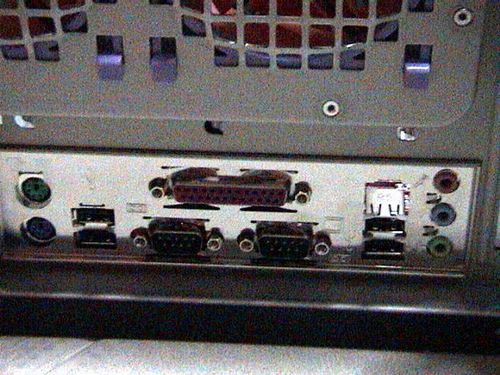
One thing that stands out of this motherboard is not only the sleek red finish but the passive heatsink on the hostbridge. MicroStar has really decided on cosmetic purposes for marketing which is really paying, a trend we can see coming in on “designer motherboards” to come in the future. On the back ports, we can see that on-board 5.1 sound is included, so is a parallel port, 2 serial and ps/2 ports and 4×2.0 USB backports.
Graphics card
Graphics on a PC usually come in 2 variants, dedicated and onboard video. If you intend to do just basic websurfing and wordprocessing, these days onboard video is good enough and allow an occasional 3D game. Otherwise, I will strongly recommend a dedicated graphics option which involves employing a video add-on card into your system.
The dedicated card I’ve got here is a Gainward Geforce 4 Ti4600 128MB Dual DVI VIVO The first impression I got on this card is woot!, this baby’s long! To get the bang of gaming, a Ti4600 is at least needed for max settings gaming experience for today’s and tomorrow’s games. As USB2.0 is already included on my sis648 mobo, firewire is not really needed, but its too, good to know that the Gainward Ti4600 bundle has a firewire pci card in too.. primary for dvd and video editng purposes- neat! On abit of history, Gainward has been in the video industry for a respectable period of time long before 3D accelerator cards came into the market. They are always in for the head to head battle with tripleX and leadtek. Well.. looks like gainward won me over!
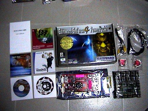
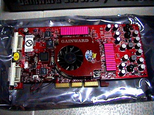
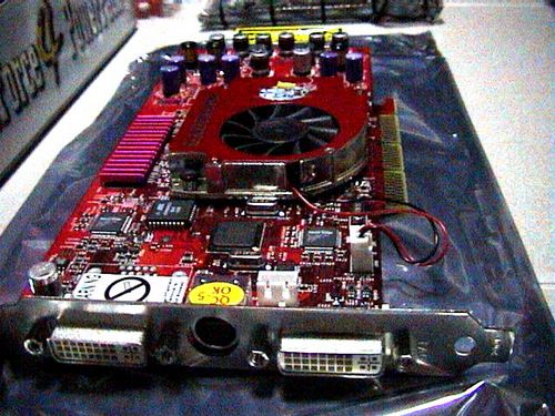
Gainward too, has quite a decent bundle for $512 SGD- full version of serious sam, windvd, winproducer and wincoder. Included are also 2 Digital(DVI) to analog converters for vga monitors, VIVO (video in, videoout) ports. With digital output now, I think it would be sometime before I switch back to analog output again! Lolz! The active fan allows heat dissipation and has thick plastic/rubber type material which I think, is polyurethane for quiet operation and optimum airflow. Also, the fan is easily detachable for any more upgrades in the future. Gainward too, has not only has GPU but memory overclocking in mind when creating this card- all the ram modules are all covered with a robust violet-red passive heatsink. As we can see above, we have dual digital (DVI) backports and the VIVO port.
Soundcard
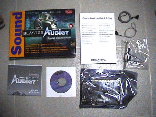
Sound blaster Audigy Though Hercules has recently released their new 7.1 soundcard, personally a 5.1 solution is more than enough for me, therefore explaining the audigy choice. As we can see the recent trend, many games are all geared towards creative new Advanced HD EAX hardware with the exceptional HW conflicts creative cards has brought to many, we can expected respectable sound from this 24-bit baby. I am expecting more from this package, esp bundled games for the EAX advanced HD technology. But sadly, Creative decided to do that for the platimum and ex range, and only a demo is included with the driver installation disc. Bundled together here are digital and analog cables for cd-rom drive connection, gaming port attachment and well, a second firewire port for the whole system!
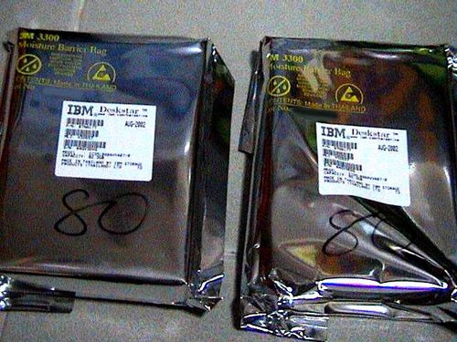
Drives
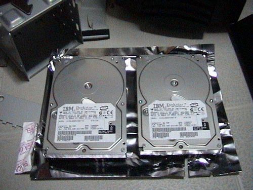
Now we are up to the drives, firstly the hard drives. I’ve got 2x80GB IBM 120GXP harddrives that makes a total of 160GB total, but judging at the capacity label, looks like I am lucky that they’ve labeled it at 82.3Gigs average for which drive, which makes it a total of 164.6GB to be exact. This is my first time in such a situation as most harddrives I own always have an eventual rating below the normal capacity, thus giving you that sour “I was cheated” taste-in-mouth-feeling. Both have a 2mb buffer and spins at 7200rpm. And personally, even with the new western digital 8MB buffer drives, performance difference is not that great though, for the outstanding difference in price between the IBM and Western Digital one.
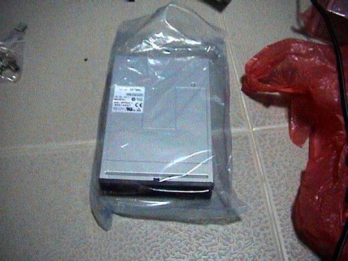
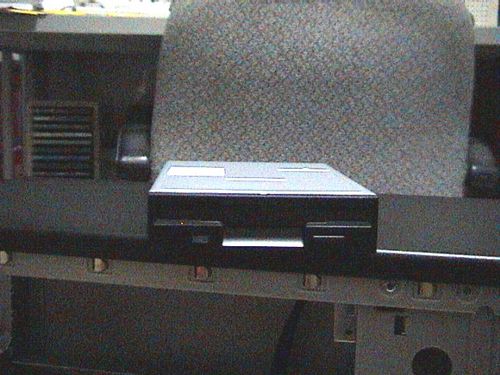
Now, to the external media IDE drives . I’ve chosen the Sony 16xDVD drive (pictured below left) and the TDK cyclone 48/24/48 CD-RW drive. Both are IDE based drives, you can get SATA equivalent of for external media drives now at a slightly increased performance from ATA-133 to 150.
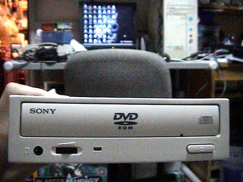
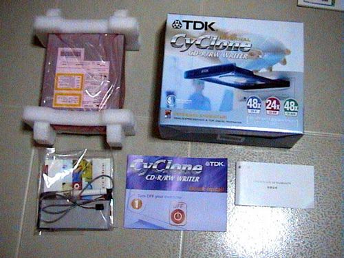
The DVD (secondary master) drive is that of an OEM version, so basically is just a bare unit. While the TDK (secondary slave) have more stuffs up it’s selves with a decent bundle with the all usual nero express/in-cd and TDK digital mix master. Good thing, as I will be using their E-IDE cables, soundcard input cables all for my master DVD drive!
Ok Lastly here, the floppy drive. What we have here is the Sony black floppy disk drive.
Power supply
The power supply unit is the heart of the system, it is where power is sent to each and every individual component in your PC. One should not let back on the PSU given it’s critical role, particularly when it fails- Better known branded PSUs such as Coolermaster, thermaltake, silverstone and Antec etc usually will not fail catropically and frying all your parts when it fails, so it pays to invest in a good unit as insurance for your PC as a whole.
I’ve chosen the Antec truepower430 firstly because I need 400W for present and future needs and secondly, because Antec has been recognized for their quality products in this sector. In the package, the system incorporates antec silent fan (low-noise technology) and taking into consideration that this is a dual fan unit, its gonna make a heck alota noise if it doesn’t have that feature.
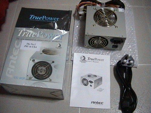
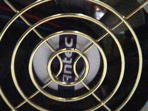
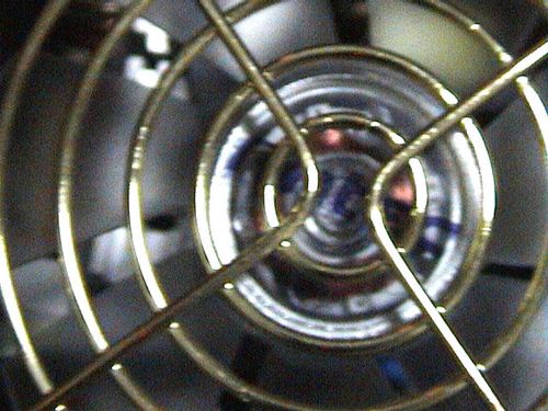
One thing which really caught my eye and impresses is the quality and looks of the fans. At the backunit fan (left top picture), the fan motor have the antec logo printed prominently onto it and is not some cheap sticker which may peel by heat of eventually, taking about quality finsh here! Secondly, the top 2nd fan have this neat transparent motor casing which the antec logo too, printed directly onto it. This is good if your casing have a top blowhole in which you can not only dissipate heat efficient but a good thing to admire (Lolz!). Peeking through the fan grills, the transformer and coils inside are all strategically placed for optimum cooling purposes too.
Casing
The casing or enclosure is where all your parts are secured in place, the size range from micro-ATX formats to ATX and SOHO server cases, depending on how much expansion space and drive slots you will require. The haul here I’ve got is the Thermal Take Xaser A5000+ case series. This is the first line of cases made by the component cooling professional. And they are really particular on the packaging here, neat job on the box.
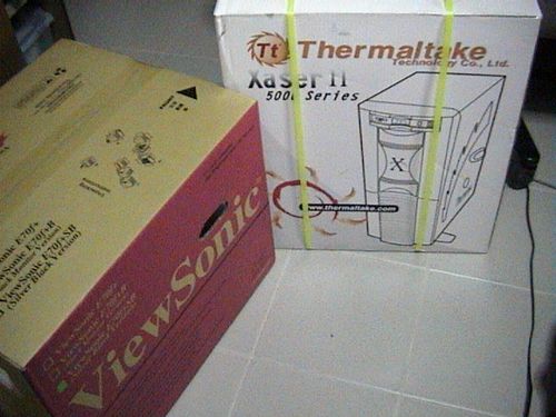
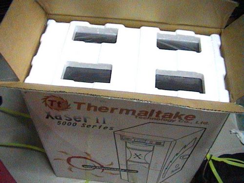
Thermaltake are sure to impress with the mid-tower server case design. Included are 5 official thermaltake silent fans (orange in colour) and the hardcano7 unit, no power supply unit included. As stated, the casing is made from 1mm SECC black Japanese steel. Being a SOHO mid tower case, it spots 4 5.25″ external bays for external media drives and 6 3.35″ bays for harddrives, floppy drives or card readers.
The hardcano is simply just a temperature monitoring module, aimed at providing information for overclockers, though rather basic in nature, the hardcano unit sure packs lots of features, starting with the large LCD panel in the center for internal temperature reading depending where would you want to put the thermal sensor probe into- CPU, memory, graphics card GPU. etc. We have a single fan switch controller on the left with 3 speed settings and 2USBs and 1firewire output ports on the right. I won’t see myself using this feature often, and might be replacing it with a more dedicated aerogate controller from coolermaster.
Monitor
The visual company, Viewsonic has this neat looking monitor which would go very well with my black, metallic theming. The E70f+ Ultrabrite 17″ flat screen monitor, Viewsonic too, has been respected for their outstanding display products, therefore explaining my choice this too.
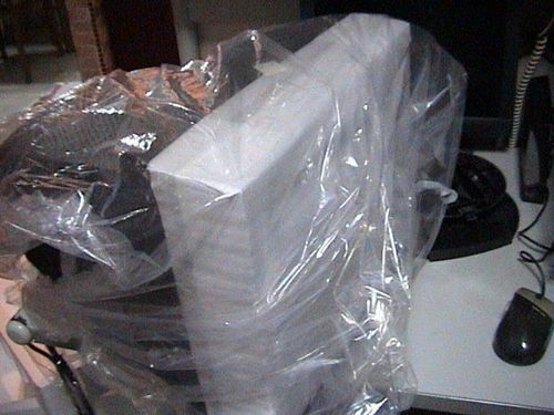
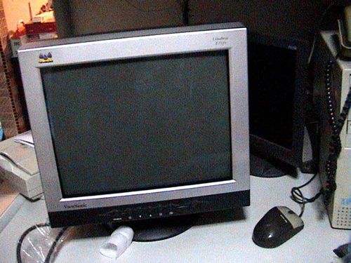
On the UltraBrite technology, Viewsonic said its for better, richer, brighter pictures for movies, gaming and graphics design. Otherwise, turn it off to normal mode for word-processing, surfing and text. And all the options can be selected with the touch of a front panel button. Neat!
RAM
Ok, lets go down the unclassified components. I’ve gotten the Winxp OEM (as pictured below), Kingston 1x512MB of DDR333 PC2700 DDR ram and the Nanoterm blue II multi-ceramic thermal compound.
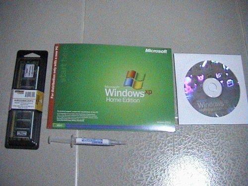
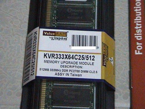
One big drawback on Kingston ram is the lack of an included heat spreader which is included with the Corsairs and Mushkins, obviously they do not really have overclocking but budget in-mind, though its a good thing to be included though.
Article table of contents
- Introductory components
- Installing the CPU & memory
- Casing & installing the motherboard (aka mobo)
- Graphics, soundcard & add-on cards
- Internal & external media drives installation
- Cabling, PSU, case LED lights & power button
- Additional cabling for output ports
- Finishing touches, power on self test (POST) & BIOS
- Operating system installation (Win XP)