Well, its late now, time to get some much needed rest from a day of writing. Finished the HTPC & External Harddrive tutorial today, updated the old DIY PC tutorial with some niffy updates, freshened up the images & made them bigger & more pleasant to the eye. The DIY computer section will now spot an idependent tutorial sub-section featuring an index for all the computer related stuffs & an FAQ from quetions I have received over the months, thats alot of work man. As promised everything will be uploaded only once everything’s finished. Whats left is the kitmodel, CPU & GPU tutorials which I aim to finish by tomorrow, more typing to go… Which makes me think: dang! I should be paid for these contributions! 
Typy sunday… or so it was

Tutorial: Upgrading your computer processor (CPU) with cleaning and thermal paste application
 with cleaning and thermal paste application")

This tutorial aims to serve as basic guide for anyone who wants to go about safe upgrading of their computer central processing unit or CPU for short. Usually I will recommend cleaning be done at least once every 2 years. This include people who wish or are intending to do an upgrade & would like to know about the steps involved before carrying out on the process themselves.
Compatibility
Before performing an upgrade, make sure that the board you are using supports the processor you are using. Consult your motherboard manual or your respective technical support when in doubt on the following specifications & check whether it teles to the processor you intend to install
Main things to check for
- Socket type (Slot? Processor bed type?)
- Pin numbers (e.g 478pins? LGA socket?)
- Front side bus (FSB in MegaHertz)
- Cache size (e.g. 533KB, 1MB or 2MB L2 cache)
- Others: (Manufacturing process)
Though there are unofficial add-ons & converters which allows processors to be upgraded to a different process, eg using Intel 478pin processors on 423pin boards. I won’t be covering that here, however, do feel free to do a search on the net for more info on such converters if you intend to “cross-jump”.
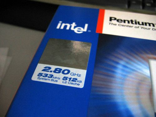
The package
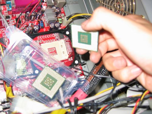
First off, for illustration we have the subject, a Intel Pentium class 4 2.80Ghz processor based on the 130 nm Northwood process 533FSB & 512KB L2 Cache (Fig 1.0) to replace my an old Pentium 4 2.53Ghz processor on a 478 pin motherboard.
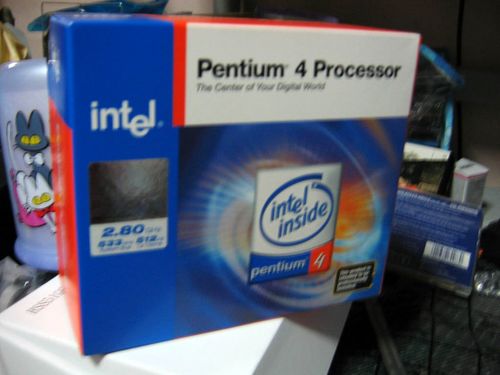
Do note that your processor may differ in specifications name or brand, but the procedures to insert the processor is the same throughout. Processors are always mounted straight onto the motherboard via a socket compatible with your chipset or silicon process, then lever locked into the socket itself. Thereafter, a heat sink and fan will be secured to the motherboard holders to lock the processor in place. For LGA processors and beyond, the logic is always the same.
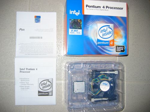
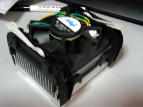
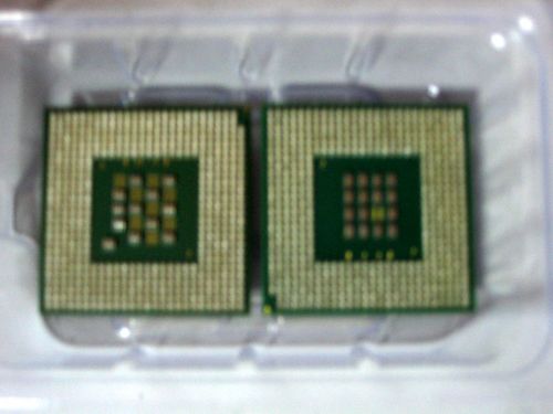
What we have in the box (Fig 2.0) is pretty limited & more or less everything of what you can get when buying off the shelf processors from your local PC parts shop. Inside we have the processor sealed in-plastic, the processor heat sink for that model & fan. Documentation included will include a simple installation manual, copyright info and the intel sticker all can be found on the left.
The swapping process
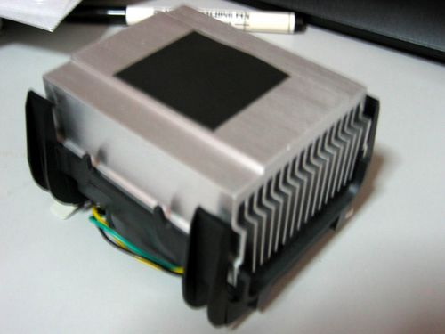
Upon opening up the the package we have the standard intel heat sink with thermal pad installed. You can choose to remove the heat pad in pace of thermal paste being applied. Alternatively you can choose to reuse back your old compatible heat sink & keep the new one for future needs or can choose to sell it instead. If you intend to overclock your processor, you might want to invest in a third party cooler which have better cooling pipes for heat dissipation and a more powerful fan for circulation.
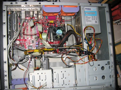
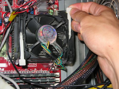
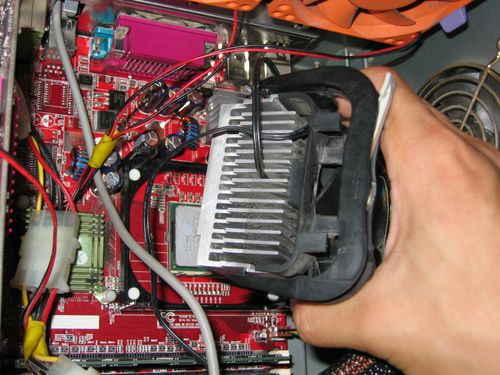
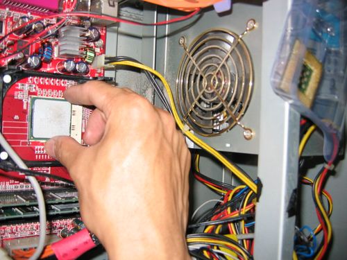
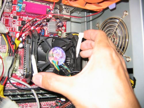
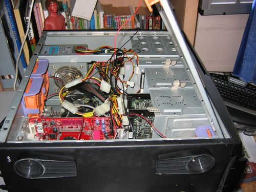
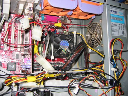
Next we start by opening the computer to be upgraded. Identify the processor by locating the large similar black fan (Fig 4.0). This applies if you are using the standard OEM heat sink & fan Intel or AMD uses, they all bare similar resemblance, only that certain designs & dimensions are different. Unplug the CPU fan cable from the motherboard usually located beside the processor. Unlock the fan holder by lifting the white locking levers shown in Fig 4.1.
Tip: Before touching any components in the casing be sure to earth your hands by touching the back metal surface of the computer casing, this is to prevent static electro damage to your components, esp when handling sensitive parts such as your processor. Alternatively you can choose to wear a static wrist band.
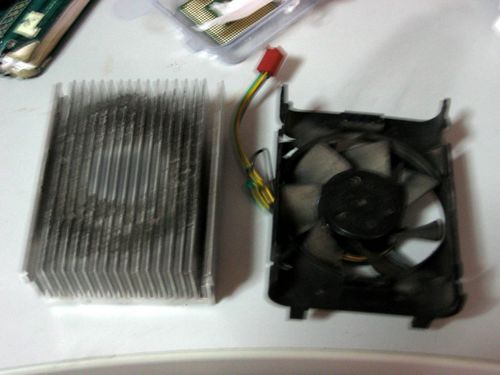
The fan should be loose once the levers are raised. To detached it from the motherboard (Fig 5.0), gently release the 4 black plastic hooks found at the corners of the heatsink holder by applying downward pressure, then lift downwards- outwards to unhook. Take caution as thin plastic frame could break if excessive pressure is applied, as so which happened to me on a few instances before, well but we always have a spare one for keeps.
Cleaning
If you intend to reuse your old heat sink, you may notice that after a few years of usage, there is nothing much left defined of the silvery heat sink shine anymore, only much of a contraption of fins most probably just back from an inferno dust trip.
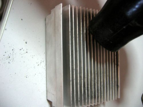
Start by using a vacuum to clear up most of the loose dirt & dust stuck to the heatsink fins. Use a scrapper or such in Fig 6.0 to remove stubborn compacted dust masses within the fin gaps. Vacuum cleanly thereafter. If you wish to install your processor straight way, try to make the process as dry as possible, which means exploding the whole heatsink in water or wiping it with damp cloth/wipes are a no no. Well, unless if you give it 1/2 – 1 day or so to completely dry. This is so as to make sure there’s no water not only on the physical surface but to be sure that no water is still harboring in the micro cracks & crevices of the heatsink, where thermal paste should be applied, thus affecting cooling efficiency.
Installing the new processor
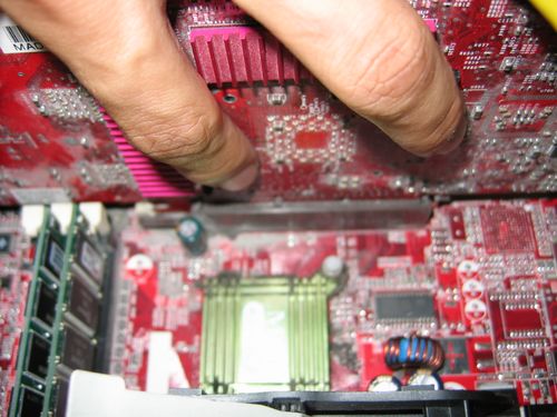
One you are done with the cleaning, you can start to prep the installation of your new processor, but first you got to remove the old. Lift the processor locking lever, remove your old processor from the processor bed. While you are at it, try to get cleaning the North brige & South bridge too (Fig 7.0) its usually a passive heatsink-like structure located near the processor & ram slots & the other near the I/O ports.
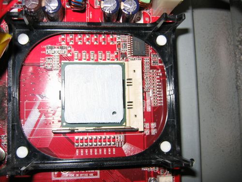
With that done, insert the new processor into the processor bed, be sure to place it the right side (Fig 7.1) up by confirming the pin count & arrangement on the processor & that on the socket/processor bed.
Alternatively, you can use the notch on the corner of the processor (Fig 8.0) as an indicator. Note that placing it incorrectly will damage the processor & board. But normal manufacturers will make things fail safe & everything can only go in- one way. Lock the locking lever till you feel a locking click & is flushed flat to the board.
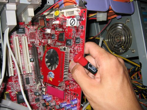
Applying thermal paste
As previously mentioned, almost all processors come with a thermal pad with you can simply just peel off and stick it to the heatsink, this is sufficient for most users who do not wish to overclock their systems. Otherwise, you can use third-party high grade thermal compound to replace the pad, which I will be using in this case. Though I had mentioned the thermal paste application procedure many times in my other tutorials, this is very much an independent tutorial too, oh well, I would go on the steps again.
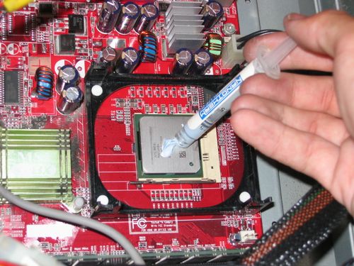
1. Apply a blob of paste onto the slotted processor (Fig 9.0)
2. Sandwich a clean, dry heatsink onto the processor blob you’ve just applied, you will get some thermal paste on the heatsink now.
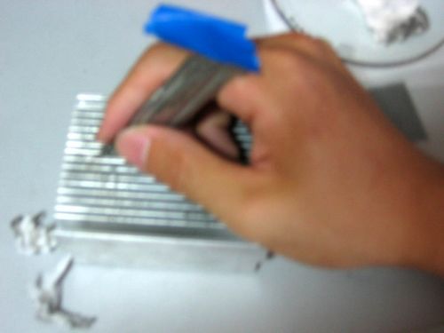
3. Using a clean finger or one wrapped in plastic, spread the paste as thoroughly & thinly as possible on the sink surface which would come in contact with the processor (Fig 11.0), this is to get the paste into the micro surface of the heatsink, I will explain more later.
4. Wipe off excess thermal paste from the heat sink. The heat sink should have a dull look on the metal now.
5. Next, gently spread the remaining thermal paste on the processor you’ve applied previously. Spread consistently, ensuring a nice thin, even surface (Fig 11.1), use a razor or card to excess paste overflowing at the edges.
The reason of spreading thermal paste on the heat sink is to ensure that all thermal paste had all entered the microscopic gaps or crevices of the heat sink metal surface. This is to ensure optimum heat conduction from the processor to the heat sink for heat to to dissipated efficient & quickly.
6. Next replace the heat sink onto the processor (Fig 12.0) & secure the 4 holding clips.
7. Lock the processor fan and heat sink onto the motherboard using the locking levers on the fan if any.
8. Plug in the CPU fan cable to the CPU fan power output on the motherboard.
All done!
With that done close up the casing & boot up, you should see the new processor registered on the power on self test (POST). Confirm the speed in you system BIOS, don’t be alarmed if the system shows another clock speed, as it takes time to adjust the multiplier to suit the new processor. Upon booting into an OS, e.g. windows, confirm the processor speed by checking under “My Computer” > “Properties”. Reboot the computer, this time the clock speed should show up correctly on POST.
That’s all folks.
New tutorials to come
I’ve been working on a few tutorials which I hope to launch altogether into the site sometime this week or so, so is the addition of a FAQ & updated tutorial of the old popular “DIY computer” article once I finish them all.
- Kit model tutorial (finally!)
- Building a HTPC (home theater PC)
- Assembling a 3.5″ External Harddrive
Upgrading your computer
- Processor (CPU)
- Graphics Card (& changing, GPU fan)
- Adding Case fans (if needed)
Stay tuned for them!
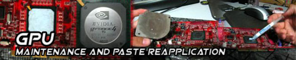
Tutorial: Graphic card GPU cooler heatsink maintenance and thermal paste re-application

The graphic processing unit (GPU) is very similar to a computer’s CPU only that it is a dedicated processor built to handle the processing of graphic related information with it’s own dedicated RAM, The logic is very similar to having a mini PC strapped inside your PC, thus reducing the load on the main processor itself and improving system performance. Thus leaving the processor to do its more dedicated “system processing” & improving overall performance. This is so since the 1997-1998 era, where the world cries for a new breed of cards- the 3D card to meet increasing gaming & workstation standards. It also marks the boom & birth of the mainstream 3D graphic processor, the tradition still carries on till now with bigger, better & improved cards, as advanced as the CPU.
GPU architecture are getting more complex, not to mention the processing power and speeds they are achieving now with or without in accordance with Moore’s law & are a force not to be reckoned with when it comes to dedicated processing power. This applies the same for other add-on cards such as sound card with their own sound processing chip, esp those found on the Creative Audigy soundcard series, for example.
Though almost all graphic cards come assembled with the embedded processor and attached heatsink, dust and dirt will over time, accumulate on the heatsink and requires cleaning- a chore often overlooked by many. This tutorial aims to teach you how to maintain your GPU in spick and span condition:
- To serve as basic guide for anyone who wish or are intending to do an upgrade & would like to know about the steps involved before carrying out on the process themselves.
- GPU fan upgrade/replacement (for more powerful cooling alternative)
- Application of thermal paste to the GPU (for improved heat dissipation & performance).
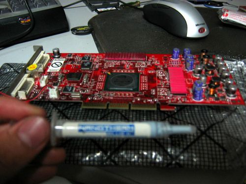
Getting to work
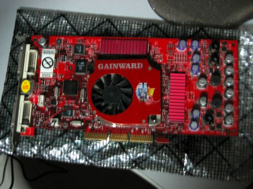
Start by opening your computer up, next, identify the graphic card. If you do not know which card it is, just check which port at the back of your PC connects or fits your monitor cable, usually there will be 2 or more outputs at the back which are either VGA, DVI (Or dual DVI) or Analog S-video outputs. Other than that, it’s usually the biggest card with a large heatsink or fan on it. Other ways of identifying will include it being topmost card on your motherboard expansion slots or the only one screwed at the slot by a lever. Be sure to earth your hands before handling any internal parts of your PC.
Your graphics card have to be of course a dedicated unit to be removed, otherwise you need not do anything if you have integrated graphics on board. Your graphics card can be attached to your computer in many formats, namely, PCI-express or PCI-E for short which comes in the 1.0 or 2.0 formats. Otherwise there is the outdated AGP (accelerated graphics port) format to the old PCI card format.
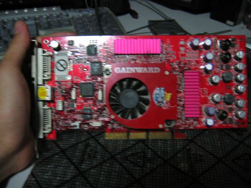
Removing the card
This card here is an AGP card, the way of installing it is rather straightforward and is same for all bus across the board such as the current PCI-E cards. You still get a fool proof slot which goes in only one way.
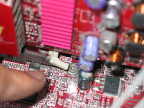
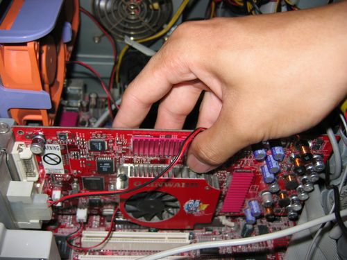
Irregardless of your graphic card slot, the card can only be removed after releasing/unlocking the locking lever found at the end of the port (Fig 2.0). If you card is held by screws, unscrews the card from the case & unplug the card from the slot (Fig 2.1). If your PC case is a tool-less one which uses levers to lock the cards in, check whether there is a dedicated lever per slot or a master one which unlocks all.
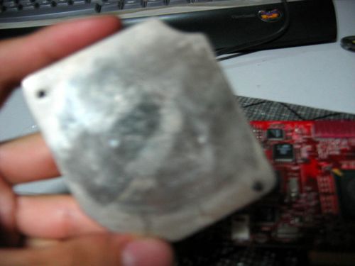
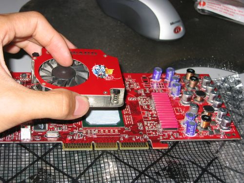
Removing the GPU fan
With the card out, note the location of the fan at the center of the card. Note that some cards uses a passive heatsink instead of an active fan, but the process too remove them are all the same, unless your OEM cooler covers your whole card, such cooling units are usually hinged & can be opened in a lid-like manner.
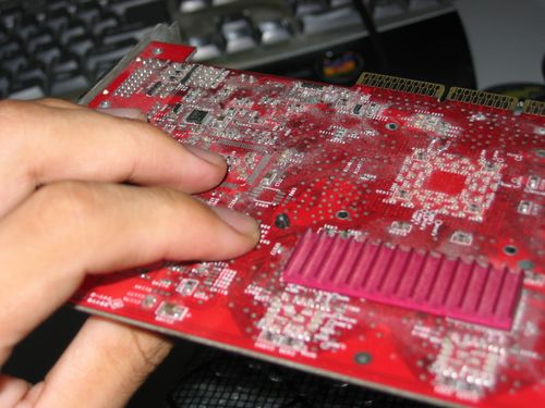
Turn the card over & you should be able to find the plastic securing locks underneath (Fig 3.1). Using a pair of small tweezers of your thumb & index finger, gently squeeze the plastic clip till its small enough to be pulled through out of the board. For most cards there are only 2 of such clips. Unplug the GPU fan from the card (Fig 4.0) & set it aside.
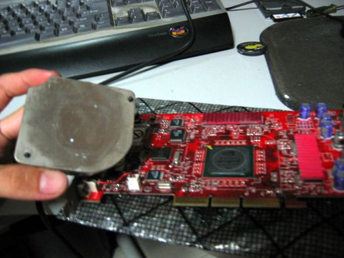
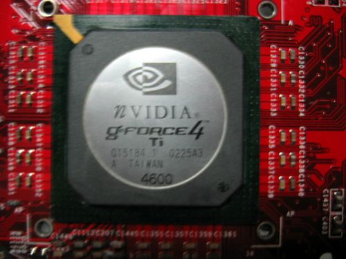
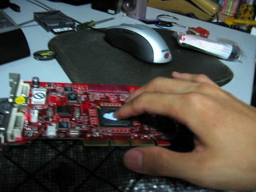
There, you’ve exposed the GPU in all its glory (Fig 4.1). There may be some white paste on it- thermal paste applied from the factory itself. From here you can choose to install a new GPU cooling fan/unit/block (e.g. for water cooling or just want a bigger, more powerful fan for GPU overclocking). Such units usually come secured in the standard similar 2 clip format, which is universal & is the same kind of mounts for the heatsinks or fans on your motherboard North/South bridge too.
Applying thermal paste
Now I will on the process of applying thermal paste to the GPU. It is very similar to applying the paste on the CPU, only that in this case the process and parts are more simplified. Well unless you have a huge custom cooler on your card.
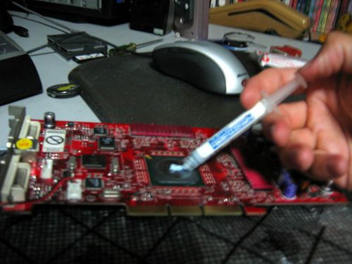
1. Apply a blob of paste onto the GPU (Fig 5.0)
2. Sandwich a clean, dry heatsink onto the GPU (you will get some paste on the cooling unit now)
3. Using a clean finger or one wrapped in plastic, spread the paste as thoroughly & thinly as possible on the cooling unit surface which would come in contact with the GPU.
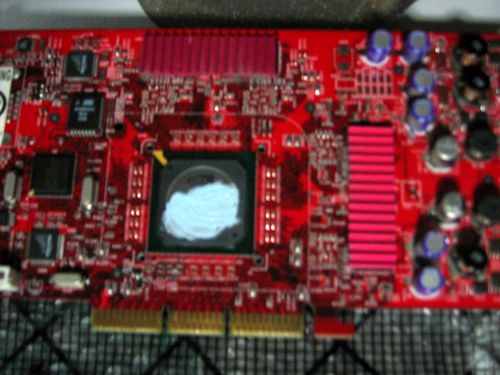
Now, all thermal paste had all entered the microscopic gaps or crevices of the cooling unit’s metal surface. This is to ensure optimum heat conduction from the GPU to the cooling unit for heat to to dissipated efficient & quickly.
4. Wipe off excess thermal paste from the cooling unit. (Fig 6.0)
5. Next, gently spread the remaining thermal paste you’ve applied on the processor previously. (Fig 6.1)
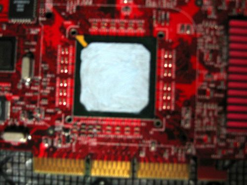
Ensure a nice thin, even spread of thermal paste (Fig 7.0), use a razor or card to excess paste overflowing at the edges. Now we are done with the application.
Replacing the card
Now with the paste applied, it’s time to put everything back together again. Whether it’s your spanking new hardware or simply just putting the old cooler back on, everything is done pretty much in reverse, and is much easier as well.
Place your cooling unit vertically over the GPU with the securing clips & mounting holes in line and slowly lower it onto the board. The cooling unit will clip onto the board easily. Ensure a good lock by momentarily suspending the card from the cooling unit itself, shaking it lightly while suspended will ensure a tight fit and the pins secured.
Now to slot the card back to the motherboard. Installation of the card now can be straight forward as the card can only go in one way. Any problems arise now may be resulted from component damage or improperly connected/unconnected cards.
Slot the card into it’s rightful slot (Fig 9.0) ensuring that the port lever is in the “locked” position (Fig 9.1) once properly seated and secured, plug in your video cables and power up both your monitor and PC, next boot up the system, the card will register itself on the top left corner of the screen before POST- a sign of a working card, then go into POST & eventually the boot up process into the OS. If you see any colour differences or the screen one particular colour (e.g pink when you are using a DVI converter, just turn off your PC and re-plug in your cable, it’s just a connection problem. Once ok, give yourself a pat on the back, you are all done!
Study in Scottland?

My mum & dad picked me up from Kranji camp where I attended the Army Open House Post function with the usual AOH creative team, Zhuang & Karpal (well its his camp). The spread was good, the highlight being the rice in squid thingy, it was of an international buffet setting with bar stools & tables to chomp on ya eats. There was the post AOH speech by CAO & commendation of the work the sponsors, exco & formations who helped & participated in the event, which wouldn’t be possible without.
On my way back home in the car, mum asked about my future study plans, well it came very much of a sudden I guess I was not really prepared for it (though I could see it coming sometime now). I asked for more time for me to think about it, well its quite a big commitment about what I am gonna take. Initially I my degree study options are limited to that in Australia, where most Singaporeans go, I could not secure a place in a local University, well maybe on a course which I really want to take, truely to my heart & not just do any degree program just for the stake of having one… Mum suggested studying in the UK, specifically Scottland. But man won’t it be very expensive? Not quite shes says, maybe the airfare, but its as affordable as studying in Australia, furthermore university rates downunder are not getting any cheaper too thesedays. Whhee, UK, scottland? sounds impressive, but I would definately have to be freaking independent for that! Not to mention the possible friends & possbile relations I would make there… *ponders* 😐
Hello college life again!
yet to come!
Tutorial: Drawing and computer coloured art – Part II Digital colouring with photoshop


Colouring in Photoshop
I use primarily Adobe PhotoShop 7.0 for computer generated art and for colouring my black & white pieces, it a very much cheaper alternative too actualy buying physical colouring tools and supplies for colour. Ulead photo express is my second most used software, though I prefer PhotoShop for its tricky yet advanced palette and brush effects.

Powering your paintbrush- workstation hardware
Photoshop can be very resource hogging at times, especially after scanning in or working with a high resolution image. This is true for the very recent releases of Adobe photoshop. What you need least is an unstable system prone to crashing once its system resources are all eaten up. Usually the “save your work every 5mins” rule tend to apply as a guide rule to prevent lost of unsaved work in a crash, but overall, a faster dedicated computer will tend to lead to more working efficiency and lesser headaches. what you need least is a crash to throw your mood and working momentum off-course.
Basically, for a basic photoshop workstation I would recommend at least a 2Ghz computer or 1.7Ghz for dual cores with at least 1GB of ram, 10GBs of free harddisk space & of course a graphics card capable of displaying higher resolutions, given you more workspace. Other comfort factors include a good precision optical mouse for accurate selection and colouring, and a reasonably large (at least 17″) CRT monitor capable of displaying colours up to 32bit accurately (not 16-bit LCD monitors as colours shown are usually not accurate).
Transferring drawings to & as CG art on the computer
To actually get started colouring in photoshop, you have to import the piece. I strongly don’t recommend taking pictures of your piece and throwing into photoshop, even in this age of how evolved digital cameras are now. Use a scanner. Start by having TWAIN or scanner utility import the scanned image to photoshop.
Layers
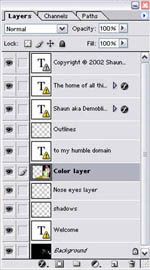
Layers had been one of the most useful features in PhotoShop since it was introduced. Though its more of an integrated palette introduced long since the photoshop series came up. It allows me to work in layers, which is handy when moving pieces of your work to be modified separately with their own properties. My typical workpiece will usually have the following basic layers created:
Layers had been one of the most useful features in PhotoShop since it was introduced. Though its more of an integrated palette introduced long since the photoshop series came up. It allows me to work in layers, which is handy when moving pieces of your work to be modified separately with their own properties. My typical workpiece will usually have the following basic layers created:
- Outlines (Lineart)
- Base (Flat) colours
- Reflections
- Shadows
- Corrections & maintenance
- Background
General workspace layout
As they are say, the bigger the better. Generally, its good to work with a large work area, where you can conveniently access all the panels and tools at hand. To achieve so, be sure to run photoshop at a minimum resolution of 1024×768. Professional displays are getting more affordable these days as well and I will recommend a proper calibrated LCD display at 24″ and above, so you will have at last 1920 of horizontal width, the higher the better.
Digital tool lineup
Next let me go through some of the basic tools you would be using in this tutorial. The default panel on the left of the workspace is known as the tool panel, conspiring of all the primary tools you need to manipulate your art piece. Anti-aliased brushes are commonly used for outlines, to give lines a more dissolving and not a straight blocky feeling. Though this was commonly known as the airbrush back in photoshop 5.0. Version 7.0 allows you to define anti-aliasing though the brush palette. The pencil tool is mostly used for colouring while the brush tool is used when varying intensities or when colour pressures are required (like giving the way for light, reflection effects & shadows). The pencil tool do not have the level of variance and control.

The lineart
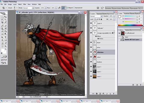
This is how a freshly scanned piece looks like into photoshop on the right. Here you can choose to crop it, clear away noise (aka”dirty scans”) in the picture using the eraser/white pencil tool or resize it to your desired dimensions. Though I would usually recommend working on the image at near scan resolution (e.g about 2000×1000 for 300dpi A4 scans) for better images as the end product would normally be compressed/minimised (i.e for the web) allowing for a smoother, sharper image.
Moreover, by doing so at least you will have a high resolution workfile for clear printouts too. When done, its time to create the outline (or lineart) layer. Cut the whole picture out using the “select all” then “layer via cut” options, then you will have a new editable layer in the layers palette consisting of this outline. Next go to this layer’s property and under “blending options” set the general blend mode to “multiply” (see picture below).
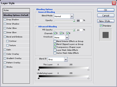
As shown above, simply select “multiply” under the outline layer’s blending options. This will allow you to see through this layer on another (superimpose). This is particularly useful for colouring the piece using another dedicated colour layer below the lineart layer without messing up the lineart layer itself, at the same time having the outline casted over the image all the time as a guide.

Adding the base colours
Next, start colouring only using the pencil tool (i.e non anti-aliased, smooth edged tool), keeping within the lines or desired image. Here is the first step to colouring where we want to quickly and effectivly fill the image with a base colour. Use larger brush sizes to effectively colour open spaces and shrink the brush accordingly for smaller, detailed colouring. Moreover, here is where the lasso tool shines, allowing you to select and colour within the selected small gaps and details without “spilling” colours.
Try to keep to one colour tone for each surface, i.e skin, metals, clothing.. etc. as more tones would be added later, remember what we want now is only the base colour. Once done, the end result is a rather complete yet flat coloured piece on the left. Tip: zoom levels in whole numbers offer the clearest & smoothest image views (i.e 25% , 50%, 100%, 200%.. etc) be sure to spend most of your time working at these resolutions, whereas those at decimeter zoom levels (i.e 16.7%, 33.3% 66.7%) usually offer crisp, more blocky views.

Reflections & shadows
Over a new overlying layer (otherwise known as the “reflections” layer), use the brush tool to paint the lights, shine & shadows casted on your figure, given your desired source of light. In this case I choose light coming from the upper left, so naturally the lighter parts will face left & any objects covering the source will have darker shades of the respective colour (not only grey or black). To effectively lighten or darken colours, use the “lighten & darken” options under the “brush property mode” palette.
In combination with the dropper tool, select a colour you want to lighten/darken, go to the colour palette to select desired shade within the spectrum & paint using the lighten & darken modes accordingly & respectively. Why use the darken/lighten modes? Its so as not to accidentally change the shade of a desired point, moreover it allows a more gradual & controllable change of shades, resulting in more natural looking reflections. Its also easiler than actually selecting the actual colour to paint on directly.

Finishing up
Finally, here is where the picture is almost done and complete. Its also the time where minor fixes or further detailing are made to make certain features stand out, therefore the need of another, I call optional “touching up” layer. Finish the picture by adding a desired background to go with the overall picture, crop or resize for exporting/saving and presto! done.
Remember, there are endless ways to create and colour a picture, this tutorial only serves as a basic guide of one of the many styles I use, and I can’t deny that I am always learning something new everyday as well. So it pays to draw and experiment with new techniques, there’s more than it meets the eye and you won’t know what you can discover along the way.
That is all I have for the tutorial for now, remember: the sky’s the limit!
Article table of contents
Line art and planning your piece
Digital colouring with Photoshop
NTLDR missing solution.
Heres to a solution to a problem I’ve been pondering upon today when building my new PC running WinXP home- a boot error from POST after recovering it from an accidental power off during formating on the initial install. Strangely, I’ve always boot from WinXp CD without much hitch as it IS infact, bootable. But this dang NTLDR missing message keeps appearing & the system just gets in & endless boot “n” loop thing without initializing install. I’ve tried what any sane person would do, creating bootable discs from MS webby to boot, even NTFS formated the corrupted formatted space 2 times as a secondary slave on my other comps, but to no avail, the message keeps appearing….
Till with a flick of luck & a random thought which flashed through my very much stressed & desperate mind, after looking at my old computer viewsonic keyboard chucked in a corner of my room. “Mmm maybe the USB drivers for the wireless keyboard are not loaded” Though trival & stupid, well at 12midnight I still trying to solve the problem, (as I said, I was desperate!) How can a new PC give so much problems? & its not even due to a hardware malfunction… Plugged in the ps2 keyboard… &that little method actually worked!- using a ps2 keyboard! 😯
I see, I see, see the problem starts AFTER post, the keyboard (any type, including wireless) will most of the time function during POST where you can access the setup, bootmenu, etc, but after that when its booting some mobos actually “switch off” the IRQ to the USB when checking for newly installed devices & assigning new IRQ numbers to PCI slots, including Firewire & USB. In other words, I can’t “press any key to start CD install” AT that particular point when its performing the IRQ check. Though the keyboard seems to be working with lights & so, but at that point, its only powered by the port itself, not accepting any inputs. So the conclusion is NEVER use USB wireless keyboards & mice when installing or running your PC for the first time. Instead, use the wired trusty ps2 ones, then switch to the USB wireless ones when you get the OS up & running with the poper drivers installed. USB keyboards may work on the first attempt for me, but in this rather funny situation, the second reinstall attempt & is indeed unique.
Well, may this be a learning experience for me & possiblity anybody who reads this post. Cheers!
Upgrade bandwagon
Yes, its the start of the long off in-lieu, started tuesday night life is always so free & fun after that. Checked out from a chalet at downtown east in the morning. & yes, there was a chalet organised by my army platoon’s specs for the whole platoon (about 30+ ppl), this time with our troopers. It was fun, we catered food from out friendly camp canteen auntie ( & jus when we thought we haven’t had enough of camp food) ate, BBQed, played rounds of armoured core 3, GT3 & dynasty warriors on playstation 2 till 4am where most of us concussed thereafter, only waking up at in glaring daylight around 9am. Neato. Checked into SimLim thereafter with Adrain & John, where I got a 2.8B Ghz P4 processor, a stick of Kingston 512MB DDR333 ram & a new Microsoft digital media pro keyboard for my new HTPC, the whole SLS is out of the 3.06B Ghz processors, very strange indeed, furthermore, the 2.8B ones are running out fast too, damn better get my hands on one or there will be no more processors around my mobo can support. 😉
I would be installing the new 2.8Ghz processor on my present workstation comp, pairing it with my current 1GB of system ram & putting the old My current P4 2.53B Ghz in the new HTPC (home theater PC). However, the latter would be using the better Audigy2 soundcard, while my workstation will use the old Audigy DE soundcard. Moreover, my current comp is as dang unstable as my vintage PI 200Mhz, mainly due to some shitty adware & spyware I’ve accumlated over the years, even anti-adwares don’t seem to get to them, it rids them but don’t stop them from coming back. Oh well, guess I would be backing up all mydata over the days, possibly on a new Iomega 80GB HD external Harddrive which I am intending to purchase soon too, then wollia! a clean format to the spick & span world of clean benchmarkable efficiency. 😀
PS: I HATE SPY/ADWARE!
Hp ipaq hx4700
Wow.. drools, looks like I can throw away my wishlist for either the Asus mypal730 or Toshiba e830. Step side, cos the HP hx4700 is here!
drool, drool, drool, drool 😈
Oh yea, on some happenings today, went for a driving lesson where my instructor Mr Tan allowed me, for the first time myself so go anywhere I want freeform driving after doing my revisions, whee freedom, multiple directional change stunts, record 1 < min parrallel & vertical parking. Furthermore, managed to get my old Sony mini-DV cam to transfer video to my computer. The main problem lies in the i-link (firewire) port on the camera which could had been unknown-ly damaged previously, so I am very much left to use the other 2 output formats, A/V ports or S-video. Checkout the new NTUC for some S-video cables which I got for 10 bucks, after a few trail & error here & there with my happauge winTV video capture & willoa! video in & smooth. Dang now I have 4 useless firewire ports on my computer.. maybe I should get a portable harddrive or something someday too....
It’s Sun-turday.
Mmm, its saturday, but it feels like sunday, partly because of the deja-vu of booking in tonight. Yes tomorrow is a work day for me. 😥 I can say that its also a very short weekend for me too, booked out of camp around 8.30am today & hello camp in less than 2 hours from now…
On a brighter side, let recap some of the happenings for the week. It started off with a nights off on tuesday for John & me when we recce-ed the AHM water point at east coast that afternoon. Our WSM, (aka angchek) allowed us to carry on & make our way home from there in the evening thereafter. The 2nd consecutive nights off is an official one on the following wednesday given by OC. However, the need to for me to go to the safti MI straight the next (thurs) morning granted me the green light to stay out by angchek, who was really a very understanding & nice guy, I salute him. Thursday was a demanding day at Safti MI, but otherwise a very fun day too (see previous blog post for more details). Work ended at about 8.30pm on that thursday where I made my way home with Zhuang to Boonlay, taking MRT & reaching home at around 9.15pm. Rushed to upload some photos & type some captions, readied my items & gear to book into camp thereafter at around 11.00pm where I met a rather cheerful OC who I told of the events of the day, esp the one with the encounter with chief of army. Very entertaining, I say.
Moreover, I forgot to mention previously that I’ve contributed 12 pull ups during my last official visit to the Safti MI army open house 2004 in count for the Guinness World Record for most number of pull ups done in a single event.
My family would be dropping by Safti MI tomorrow for army open house, the event which I had been so painstalking preparing for the last few months, too bad as an official for the event, I won’t be able to join them- something my mum told me would be very much better if I could follow. However, I have nothing much to worry, they will have lots of fun there, as part of the committee, I can guarantee it. 😀
There will be a long holiday break coming up next week in compensation of the working days spent for the event. Would most probably book out on next wednesday night & break lasting till the upcoming sunday thereafter. Furthermore I would clear an off owned to me on that following monday, the 13th of september to celebrate my mum’s birthday. 😳
And finally, you can check out the final uploaded albums of both the Army Open House 2004 photos in the site’s National service photo gallery.
Mingle with the stars.
And so it was the visit to the first opening day of the Army Open House 2004, held at SAFTI MI, Singapore.
Its started with an innocent visit to the MI to check out the progress & experience the action we had been planning & promoting so far, very much a welcome to relax & enjoy the day. Met up with zhuang & karpal at the busstop at 7.30am & made our way into the hotpot. Met up with SSG Ken & Maj Goh where we got our official passes & attended chief armour officer’s “motivational talk” at the mini stage. Helped in the packing of the media goodie bag thereafter (it will always find us) which we too, were issued one each consisting of a dryfit AOH polo shirt, cap, badge & litle niffy items, dirnks & snacks. When thats done, we very much went around taking pictures leisurely checking out the displays at the neat parade square & stuffs, not to mention mixing around with school children who came & experienced the fun headon around noon. Quite a fun bunch. Dragged ourselves to the MI library where I borrowed some military manuals our OC wanted us to research on.
There was free food from our sponsors KFC, thus saving us some cash. The life slacked in the afternoon deep in the air-conditioned corners of OCS main building. Then came the rather 😯 interesting news of us (esp me) being the Chief of Army’s personal photographer.. ahha challenging… & so there I was meeting up with Chief of Army later in the evening to take pictures of him & his family, going on the live safari ride with him, the MI army rides & following him round the exhitbits & the parade square thereafter. It seems that COA have this “repelling power” to officers, esp the Majors & LTCs who seem to undergo “sponateous replusion” whenever chief comes in their way… weird… Anyway, I was just a photographer. 😉
With that done, why not feast yourself & check out the photos (& that with the chief of army) of the event here! maybe I might consider submitting them to the digital photography competition. (Note: mind the photo captions, they are not all fully up yet, woulda be workin on it on my next bookin!)
Not too bad after all
Here I am at home enjoying whats left of my weekend.
Initially, tomorrow is supposed to be an off in-lieu in compensation of the burning of the upcoming weekend due to the army open house event. But it was taken away at the last minute, due to some AOH live firing issues on my company side. Tested is my new camera too which worked flawlessly to keep up with our ever hungry demands for photos. The eventual good news is that I would be getting an off in return for spending that sunday at work, well sometime in the days to come.
And so, stuff on the roadshow, it turned out to be quite a fun event, with kids, camo & crowds & stuffs, not to mention free pizza from our food sponsor, pizza hut.
Uploaded already are pictures of the event- The AOH Roadshow @ Toa Payoh HDB Hub!