
This tutorial aims to serve as basic guide for anyone who wants to go about safe upgrading of their computer central processing unit or CPU for short. Usually I will recommend cleaning be done at least once every 2 years. This include people who wish or are intending to do an upgrade & would like to know about the steps involved before carrying out on the process themselves.
Compatibility
Before performing an upgrade, make sure that the board you are using supports the processor you are using. Consult your motherboard manual or your respective technical support when in doubt on the following specifications & check whether it teles to the processor you intend to install
- Socket type (Slot? Processor bed type?)
- Pin numbers (e.g 478pins? LGA socket?)
- Front side bus (FSB in MegaHertz)
- Cache size (e.g. 533KB, 1MB or 2MB L2 cache)
- Others: (Manufacturing process)
Though there are unofficial add-ons & converters which allows processors to be upgraded to a different process, eg using Intel 478pin processors on 423pin boards. I won’t be covering that here, however, do feel free to do a search on the net for more info on such converters if you intend to “cross-jump”.
The package
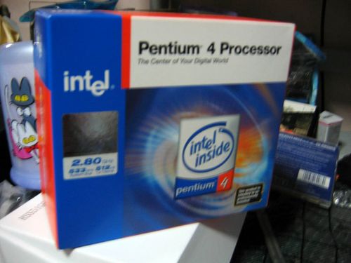
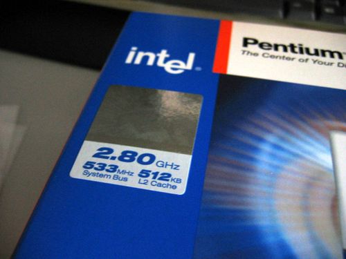
First off, for illustration we have the subject, a Intel Pentium class 4 2.80Ghz processor based on the 130 nm Northwood process 533FSB & 512KB L2 Cache (Fig 1.0) to replace my an old Pentium 4 2.53Ghz processor on a 478 pin motherboard.
Do note that your processor may differ in specifications name or brand, but the procedures to insert the processor is the same throughout. Processors are always mounted straight onto the motherboard via a socket compatible with your chipset or silicon process, then lever locked into the socket itself. Thereafter, a heat sink and fan will be secured to the motherboard holders to lock the processor in place. For LGA processors and beyond, the logic is always the same.
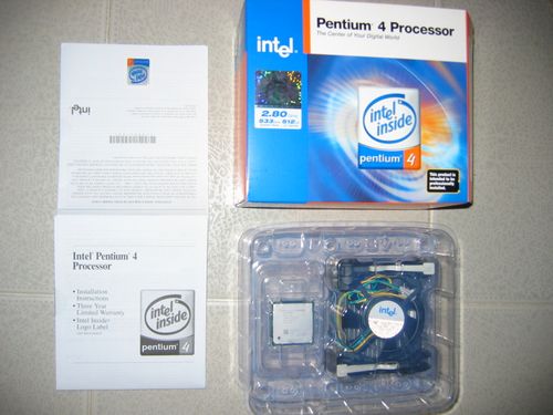
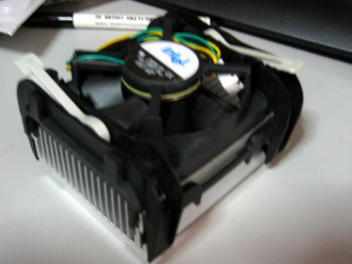
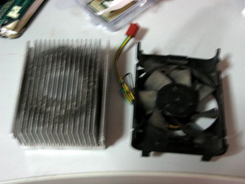
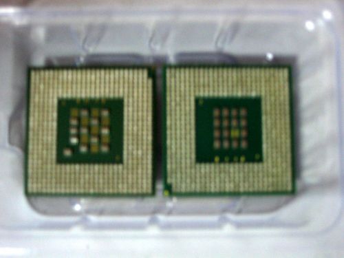
What we have in the box (Fig 2.0) is pretty limited & more or less everything of what you can get when buying off the shelf processors from your local PC parts shop. Inside we have the processor sealed in-plastic, the processor heat sink for that model & fan. Documentation included will include a simple installation manual, copyright info and the intel sticker all can be found on the left.
The swapping process
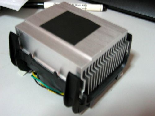
Upon opening up the the package we have the standard intel heat sink with thermal pad installed. You can choose to remove the heat pad in pace of thermal paste being applied. Alternatively you can choose to reuse back your old compatible heat sink & keep the new one for future needs or can choose to sell it instead. If you intend to overclock your processor, you might want to invest in a third party cooler which have better cooling pipes for heat dissipation and a more powerful fan for circulation.
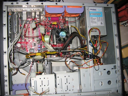
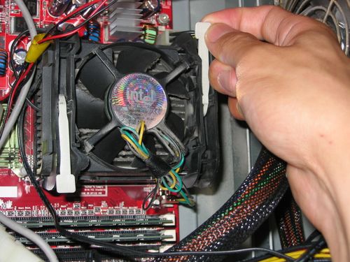
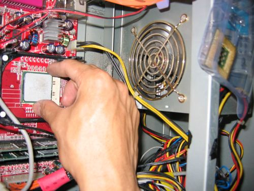
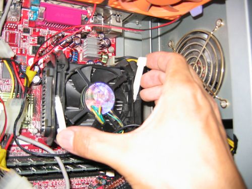
Next we start by opening the computer to be upgraded. Identify the processor by locating the large similar black fan (Fig 4.0). This applies if you are using the standard OEM heat sink & fan Intel or AMD uses, they all bare similar resemblance, only that certain designs & dimensions are different. Unplug the CPU fan cable from the motherboard usually located beside the processor. Unlock the fan holder by lifting the white locking levers shown in Fig 4.1.
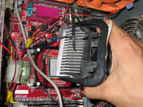
The fan should be loose once the levers are raised. To detached it from the motherboard (Fig 5.0), gently release the 4 black plastic hooks found at the corners of the heatsink holder by applying downward pressure, then lift downwards- outwards to unhook. Take caution as thin plastic frame could break if excessive pressure is applied, as so which happened to me on a few instances before, well but we always have a spare one for keeps.
Cleaning
If you intend to reuse your old heat sink, you may notice that after a few years of usage, there is nothing much left defined of the silvery heat sink shine anymore, only much of a contraption of fins most probably just back from an inferno dust trip.
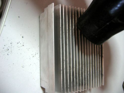
Start by using a vacuum to clear up most of the loose dirt & dust stuck to the heatsink fins. Use a scrapper or such in Fig 6.0 to remove stubborn compacted dust masses within the fin gaps. Vacuum cleanly thereafter. If you wish to install your processor straight way, try to make the process as dry as possible, which means exploding the whole heatsink in water or wiping it with damp cloth/wipes are a no no. Well, unless if you give it 1/2 – 1 day or so to completely dry. This is so as to make sure there’s no water not only on the physical surface but to be sure that no water is still harboring in the micro cracks & crevices of the heatsink, where thermal paste should be applied, thus affecting cooling efficiency.
Installing the new processor
One you are done with the cleaning, you can start to prep the installation of your new processor, but first you got to remove the old. Lift the processor locking lever, remove your old processor from the processor bed. While you are at it, try to get cleaning the North brige & South bridge too (Fig 7.0) its usually a passive heatsink-like structure located near the processor & ram slots & the other near the I/O ports.
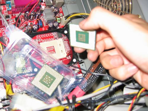
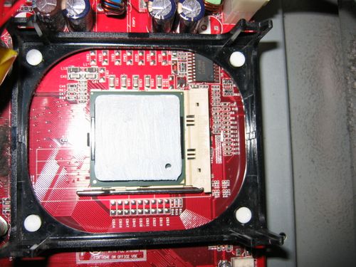
With that done, insert the new processor into the processor bed, be sure to place it the right side (Fig 7.1) up by confirming the pin count & arrangement on the processor & that on the socket/processor bed.
Alternatively, you can use the notch on the corner of the processor (Fig 8.0) as an indicator. Note that placing it incorrectly will damage the processor & board. But normal manufacturers will make things fail safe & everything can only go in- one way. Lock the locking lever till you feel a locking click & is flushed flat to the board.
Applying thermal paste
As previously mentioned, almost all processors come with a thermal pad with you can simply just peel off and stick it to the heatsink, this is sufficient for most users who do not wish to overclock their systems. Otherwise, you can use third-party high grade thermal compound to replace the pad, which I will be using in this case. Though I had mentioned the thermal paste application procedure many times in my other tutorials, this is very much an independent tutorial too, oh well, I would go on the steps again.
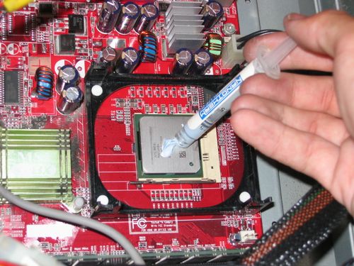
1. Apply a blob of paste onto the slotted processor (Fig 9.0)
2. Sandwich a clean, dry heatsink onto the processor blob you’ve just applied, you will get some thermal paste on the heatsink now.
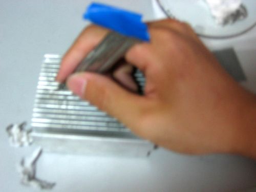
3. Using a clean finger or one wrapped in plastic, spread the paste as thoroughly & thinly as possible on the sink surface which would come in contact with the processor (Fig 11.0), this is to get the paste into the micro surface of the heatsink, I will explain more later.
4. Wipe off excess thermal paste from the heat sink. The heat sink should have a dull look on the metal now.
5. Next, gently spread the remaining thermal paste on the processor you’ve applied previously. Spread consistently, ensuring a nice thin, even surface (Fig 11.1), use a razor or card to excess paste overflowing at the edges.
The reason of spreading thermal paste on the heat sink is to ensure that all thermal paste had all entered the microscopic gaps or crevices of the heat sink metal surface. This is to ensure optimum heat conduction from the processor to the heat sink for heat to to dissipated efficient & quickly.
6. Next replace the heat sink onto the processor (Fig 12.0) & secure the 4 holding clips.
7. Lock the processor fan and heat sink onto the motherboard using the locking levers on the fan if any.
8. Plug in the CPU fan cable to the CPU fan power output on the motherboard.
All done!
With that done close up the casing & boot up, you should see the new processor registered on the power on self test (POST). Confirm the speed in you system BIOS, don’t be alarmed if the system shows another clock speed, as it takes time to adjust the multiplier to suit the new processor. Upon booting into an OS, e.g. windows, confirm the processor speed by checking under “My Computer” > “Properties”. Reboot the computer, this time the clock speed should show up correctly on POST.
That’s all folks.